
sales06@switek.biz

+86 186 5927 5869

Shopping

Subscrib to Us
sales06@switek.biz
+86 186 5927 5869
Shopping
Subscrib to Us
Keywords:Panasonic A6 Servo Motor, Panasonic A6 Servo Motor Driver, Panasonic A6 Servo Motor setting instruction
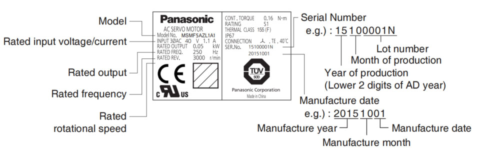
The name plate of the servo motor and driver provide an overall guideline of the motor and driver, here in this chapter we're explaining in detail the meaning of the datas on the name plate of the Panasonic A6 series of AC servo and motor.
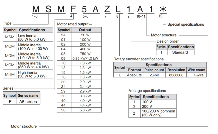
MSMF (Below ☐80)
| Symbol | Shaft | Holding brake | Oil seal | Motor I/F | |||||
|---|---|---|---|---|---|---|---|---|---|
| 10 dig | 11 dig | Round | Key way Threaded | Without | With | Without | With | Connector type | Leadwire type |
| A | 1 | • | • | • | • | ||||
| A | 2 | • | • | • | • | ||||
| B | 1 | • | • | • | • | ||||
| B | 2 | • | • | • | • | ||||
| C | 1 | • | • | • | • | ||||
| C | 2 | • | • | • | • | ||||
| D | 1 | • | • | • | • | ||||
| D | 2 | • | • | • | • | ||||
| S | 1 | • | • | • | • | ||||
| S | 2 | • | • | • | • | ||||
| T | 1 | • | • | • | • | ||||
| T | 2 | • | • | • | • | ||||
| U | 1 | • | • | • | • | ||||
| U | 2 | • | • | • | • | ||||
| V | 1 | • | • | • | • | ||||
| V | 2 | • | • | • | • | ||||
Note → • For details of specific model, refer to the Dimensions of Supplement.
Related page → • P.1-19 "Check of the Combination of the Driver and Motor" • P.7-84 to 7-107 "Dimensions of motor"
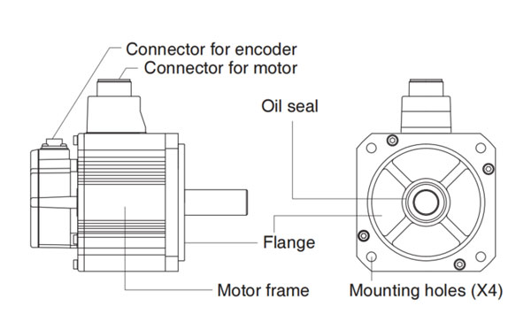
Motor structure
MQMF, MHMF (Below ☐80)
| Symbol | Shaft | Holding brake | Oil Seal | Motor I/F | ||||||
|---|---|---|---|---|---|---|---|---|---|---|
| 10 dig | 11 dig | Round | Key way Threaded | Without | With | Without | With | With (Protective lip) | Connector type | Leadwire type |
| A | 1 | • | • | • | • | |||||
| A | 2 | • | • | • | • | |||||
| B | 1 | • | • | • | • | |||||
| B | 2 | • | • | • | • | |||||
| C | 1 | • | • | • | • | |||||
| C | 2 | • | • | • | • | |||||
| C | 3 | • | • | • | • | • | ||||
| C | 4 | • | • | • | • | • | ||||
| D | 1 | • | • | • | • | |||||
| D | 2 | • | • | • | • | |||||
| D | 3 | • | • | • | ||||||
| D | 4 | • | • | • | ||||||
| S | 1 | • | • | • | • | |||||
| S | 2 | • | • | • | • | |||||
| T | 1 | • | • | • | • | |||||
| T | 2 | • | • | • | • | |||||
| U | 1 | • | • | • | • | |||||
| U | 2 | • | • | • | • | |||||
| U | 3 | • | • | • | • | |||||
| U | 4 | • | • | • | • | |||||
| V | 1 | • | • | • | • | |||||
| V | 2 | • | • | • | • | |||||
| V | 3 | • | • | • | • | |||||
| V | 4 | • | • | • | • | |||||
MSMF, MDMF, MGMF, MHMF (Above ☐80)
| Symbol | Shaft | Holding brake | Oil seal | Motor I/F | |||||
|---|---|---|---|---|---|---|---|---|---|
| 10 dig | 11 dig | Round | Key way Threaded | Without | With | With | With (Protective lip) | Connector JN2 | Connector JL10 |
| C | 5 | • | • | • | • | ||||
| C | 6 | • | • | • | • | ||||
| C | 7 | • | • | • | • | ||||
| C | 8 | • | • | • | • | ||||
| D | 5 | • | • | • | • | ||||
| D | 6 | • | • | • | • | ||||
| D | 7 | • | • | • | • | ||||
| D | 8 | • | • | • | • | ||||
| G | 5 | • | • | • | • | ||||
| G | 7 | • | • | • | • | ||||
| G | 8 | • | • | • | • | ||||
| H | 5 | • | • | • | • | ||||
| H | 6 | • | • | • | • | ||||
| H | 7 | • | • | • | • | ||||
| H | 8 | • | • | • | • | ||||
Note → • For details of specific model, refer to the Dimensions of Supplement.
Related page → • F.1-19 "Check of the Combination of the Driver and the Motor" • P.7-84 to 7-107 "Dimensions of motor"
•MSMF 50 W to 1.0kW (☐80)
•MHMF 50 W to 1.0kW (☐80)
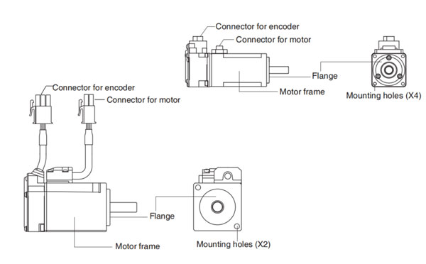
•MQMF 100 W to 400W
e.g.): Low inertia type (MSMF series, 50W), High inertia type (MHMF series, 50W)
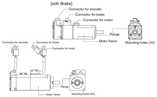
•MSMF 1.0 kW (☐100) to 5.0kW
•MDMF 1.0 kW to 5.0kW
•MGMF 850 W to 4.4kW
•MHMF 1.0 kW (☐130) to 5.0 kW
e.g.): Middle inertia type (MDMF series, 1.0 kW)
Note → For details of specific model, refer to the Dimensions of Supplement. (P.7-84 to 7-107)


