switek email

sales06@switek.biz

switek whatsapp

+86 186 5927 5869

Shopping

.

HIGH SPEED IML ROBOT

Keywords:Panasonic A6 Servo Installation Instruction, Panasonic A6 Driver, Panasonic A6 Series Servo Motor Manual

Panasonic A6 Motor & Driver Instruction 3.4 Inputs and outputs on connector X4 — Interface Circuit (Input)

Abstract

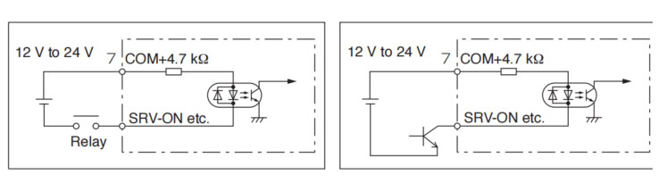
Here in this chapter is the wiring instruction of input/out connecting to the contacts of switches and relays, or open collector output transistors.
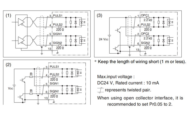
Input Circuit
  • Connect to contacts of switches and relays, or open collector output transistors.
  • When you use contact inputs, use the switches and relays for micro current to avoid contact failure.
  • Make the lower limit voltage of the power supply (12V to 24V) as 11.4V or more in order to secure the primary current for photocouplers.
  • panasonic a6 servo motor
  • 10 sysems: SI1 to SI10. For assign and function, refer to P.3-40 to P.3-45.
  1. Line driver I/F (Permissible max, input frequency of command pulse input signal.: 500 kpulse/s)
    • This signal transmission method has better noise immunity. We recommend this to secure the signal transmission.
  2. Open collector I/F (Permissible max. inout frequency of command pulse input signal.: 200 kpulse/s)
    • The method which uses an external control signal power supply (VDC)
      VDC Specifications
      12V 820 Ω 1/2W
      24V 2 kΩ 1/2W
      (VDC - 1.5)/(R+220) = 10mA
    • Current regulating resistor (R) corresponding to VDC is required in this case.
    • Connect the specified resister as below.
    • (R) should be placed close to the driver for effective noise reduction.
  3. Open collector I/F (Permissible max. input frequency of command pulse input signal.: 200 kpulse/s)
    • Connecting diagram when a current regulating resistor is not used with 24V power supply.
      panasonic a6 servo motor
    • 1 system: Pl1. For function, refer to P.3-38, P.3-39.

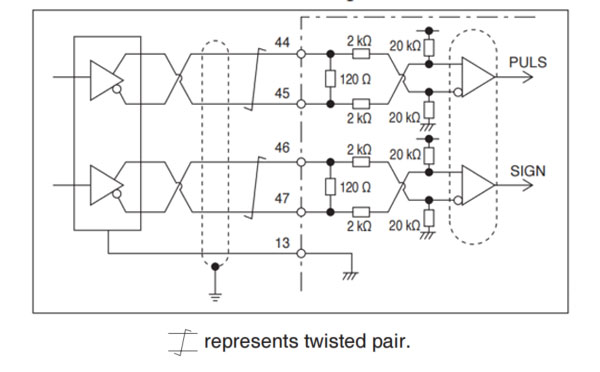
Line driver I/F (Permissible max. input frequency of command pulse input signal.: 8 Mpulse/s)

  • This signal transmission method has better noise immunity.
    We recommend this to secure the signal transmission when line driver I/F is used.
    panasonic a6 servo motor
  • 1 system: P12. For function, refer to P.3-38, P.3-39.

  • It goes through 3 systems, AI1 to AI3.
  • Max. permissible input voltage to each input is ±V.
    For input impedance of each input, refer to the right Fig.
  • When you compose a simple command circuit using variable resistor (VR) and register R, connect as the right Fig. shows. When the variable range of each input iss made as -10V to + 10V, use VR with 2 kΩ, B-characteristics, 1/2 W or larger, R with 200 Ω, 1/2 W or larger.
  • A/D converter resolution of each command input is as follows.
    (1) ADC1: 16-bit (AI1)
    (2) ADC2: 12-bit (AI2, AI3)
    panasonic a6 servo motor
  • For function, refer to P.3-46, P.3-47.

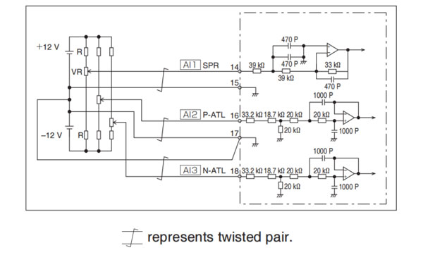
Only for the standard type and communication type are not provided with analog input.


PanasonicA6 Operating Instruction

Email: sales06@switek.biz

WhatsApp

WeChat