
sales06@switek.biz

+86 186 5927 5869

Shopping

Subscrib to Us
sales06@switek.biz
+86 186 5927 5869
Shopping
Subscrib to Us
Keywords:Panasonic A6 Servo Installation Instruction, Panasonic A6 Driver, Panasonic A6 Series Servo Motor Manual
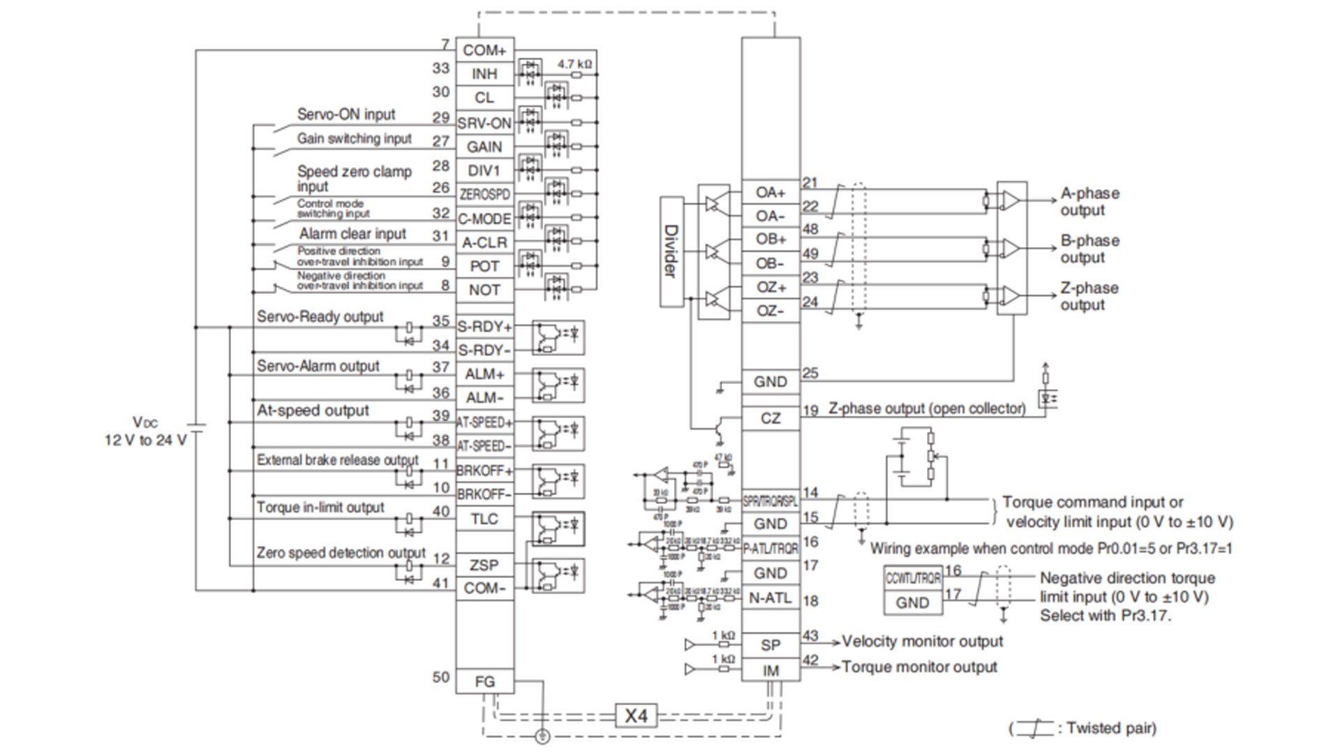
The control block diagram of the Panasonic A6 series AC servo motor driver will help the automation system designer better understand the control philosophy of the motor, here in this chapter we'll show example of control mode specific wiring.
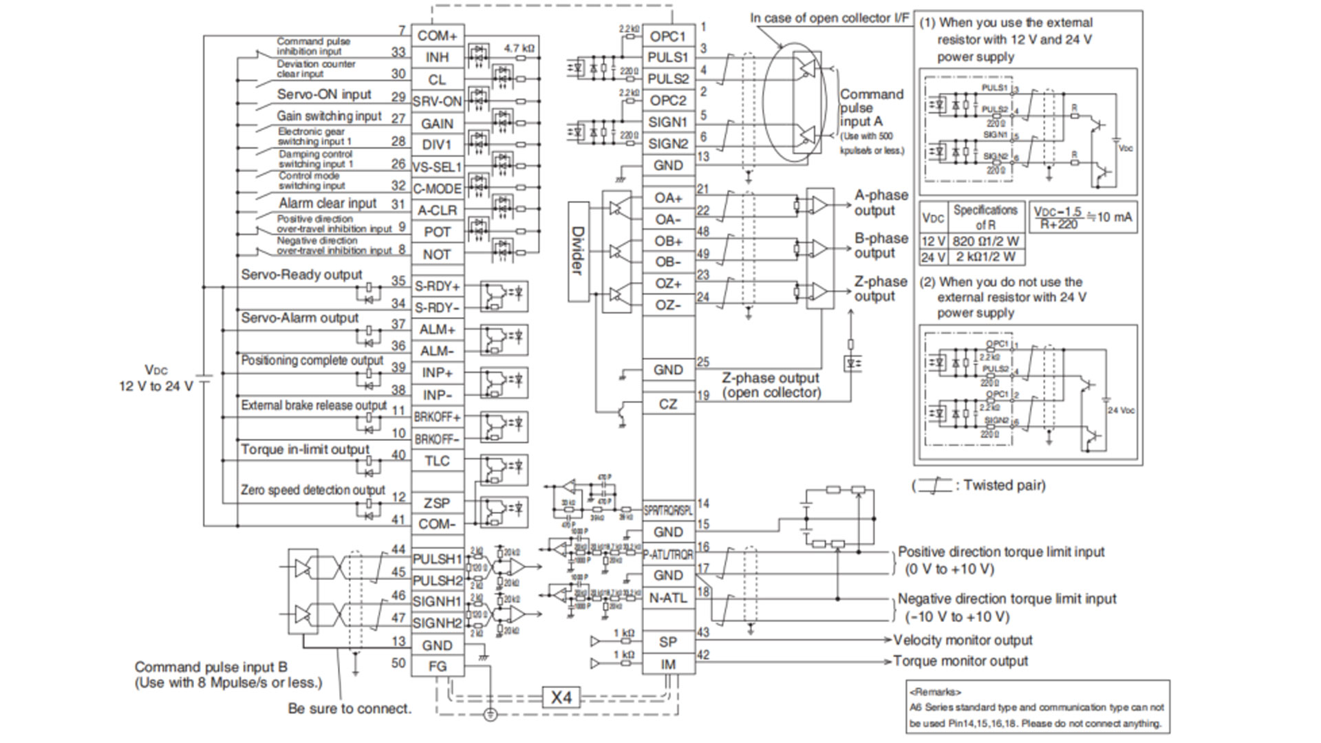
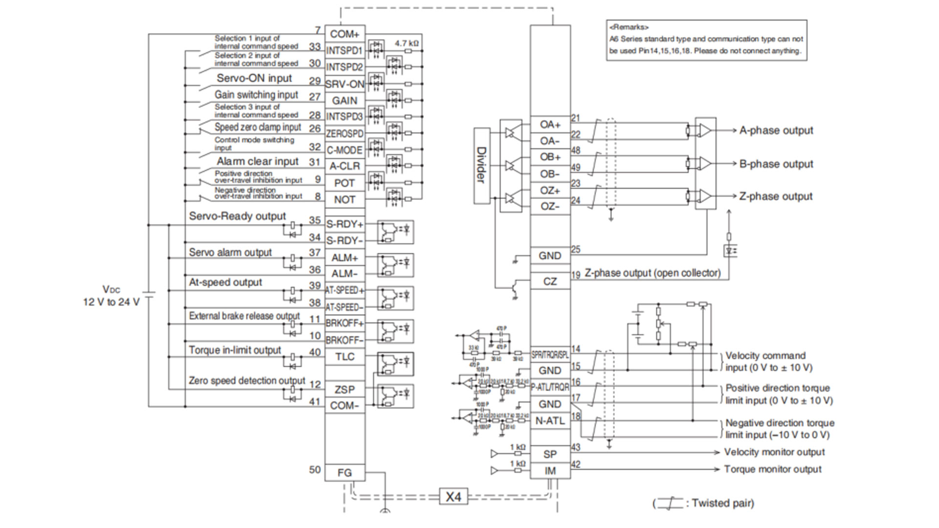
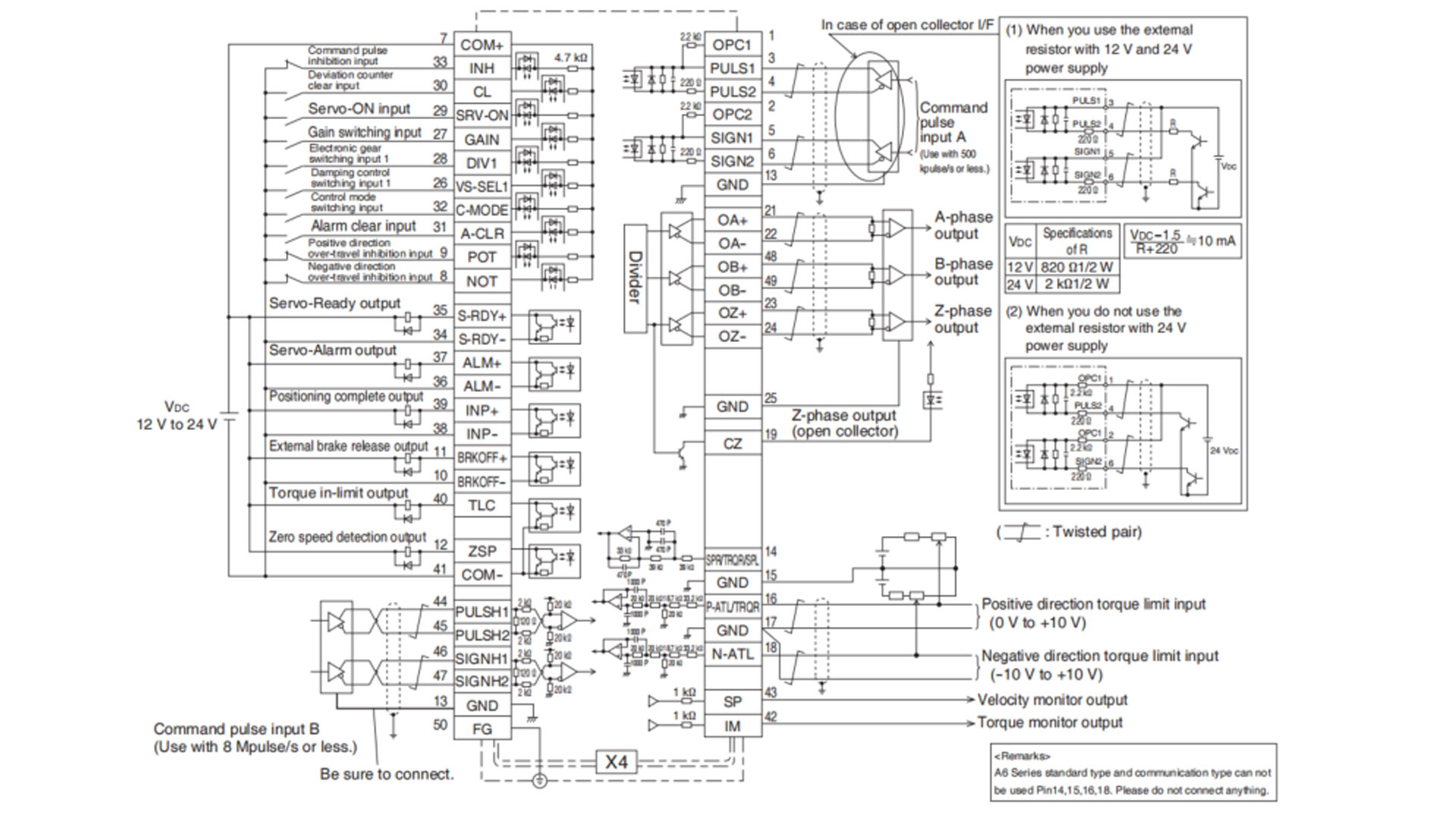
• The function of the following pin can be changed using parameters. (Refer to P.4-38)
Input (Position): 8, 9, 26, 27, 28, 29, 31, 32 Output: 10-11, 12, 34-35, 36-37, 38-39, 40
Input (Velocity): 8, 9, 26, 27, 28, 29, 30, 31, 32, 33 Output: 10-11, 12, 34-35, 36-37, 38-39, 40
* Pins in the figure above represent default parameter values.
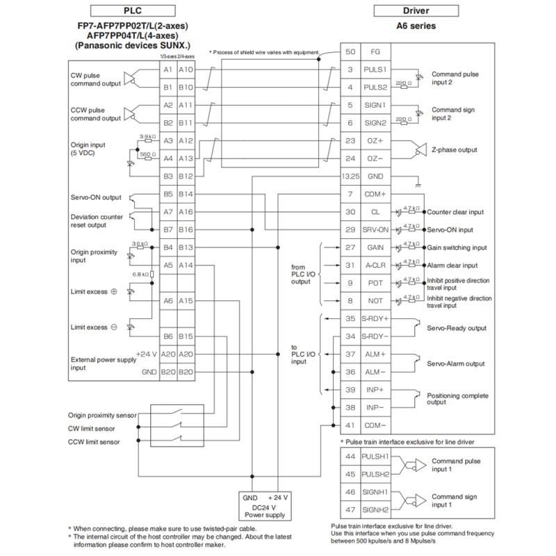
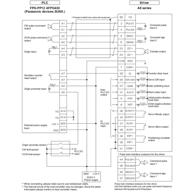
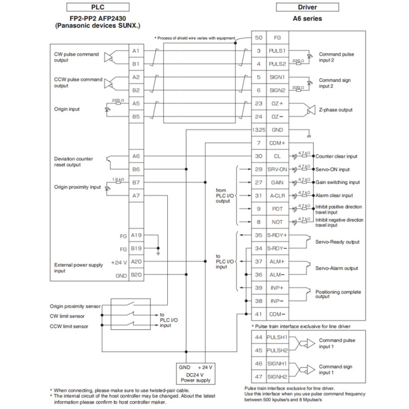
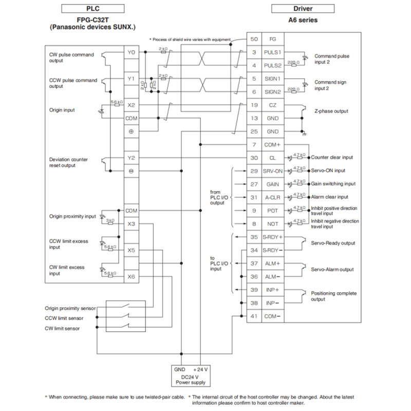
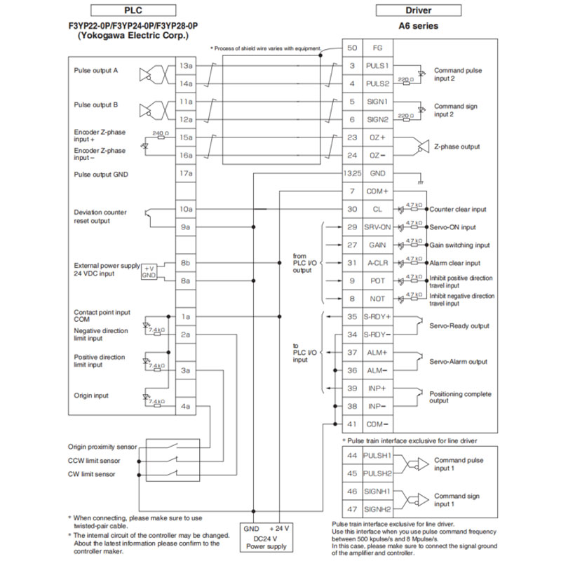
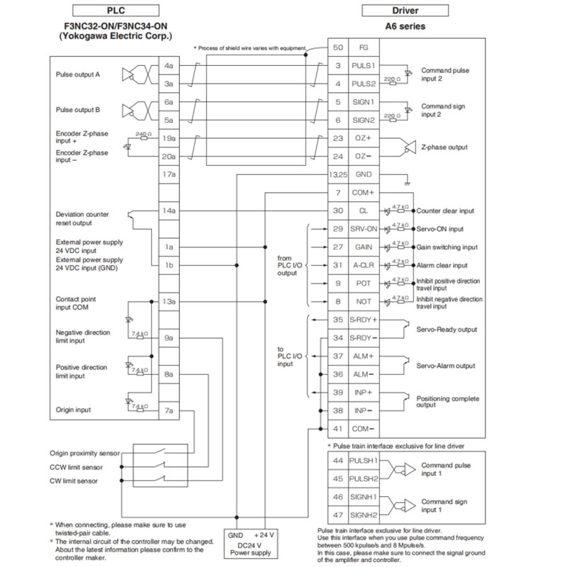
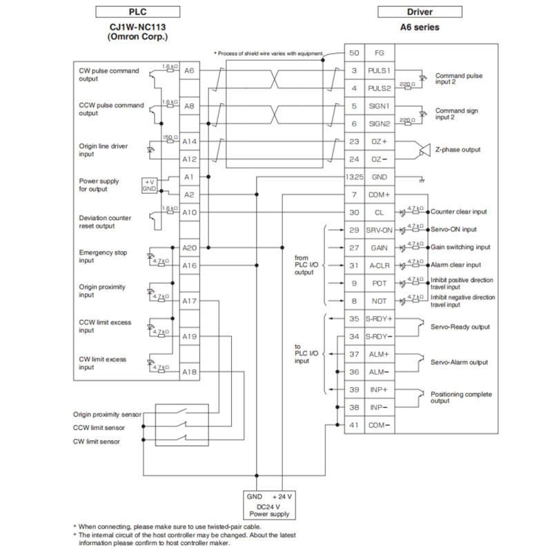
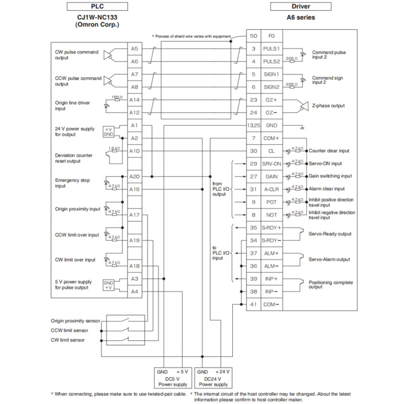
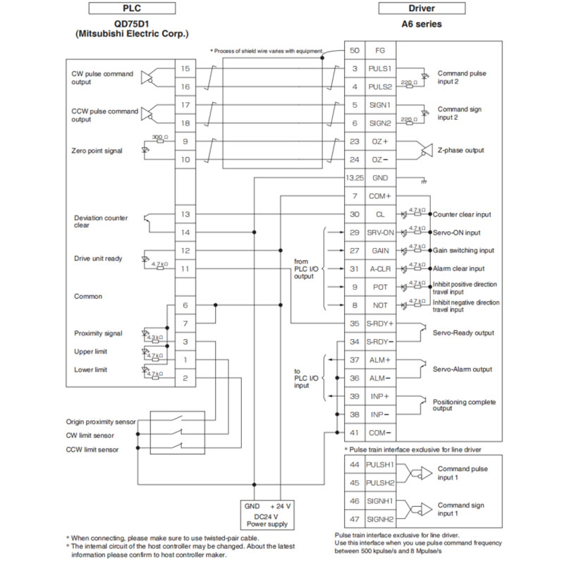
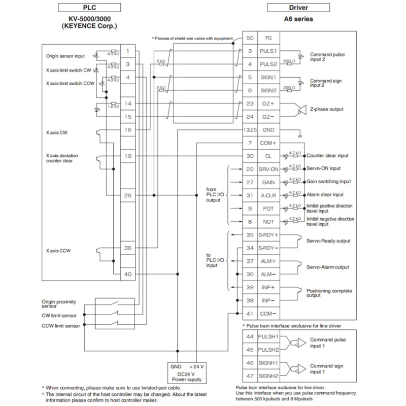
 represents twisted pari wire.
•P.3-33 "Inputs and outputs on connector X4"


