
sales06@switek.biz

+86 186 5927 5869

Shopping

Subscrib to Us
sales06@switek.biz
+86 186 5927 5869
Shopping
Subscrib to Us
Keywords:Panasonic A6 Servo Installation Instruction, Panasonic A6 Driver, Panasonic A6 Series Servo Motor Manual
The correct setup of the parameter and mode of the Panasonic A6 series of servo will ensure the proper working of the Panasonic A6 series of motor and the stability of your machineries and automation system.
| Parameter No. | Title | Range | Default | Unit | Turning on of power supply | Related Control Mode | Detail page | ||||||
|---|---|---|---|---|---|---|---|---|---|---|---|---|---|
| Class | No. | A,B-frame | C-frame | D,E,F-frame | P | S | T | F | |||||
| 0 | 00 | Rotational direction setup | 0 to 1 | 1 | — | ○ | ○ | ○ | ○ | ○ | 4-6 | ||
| 0 | 01 | Control mode setup | 0 to 6 | 0 | — | ○ | ○ | ○ | ○ | ○ | |||
| 0 | 02 | Real-time auto-gain tuning setup | 0 to 6 | 1 | — | ○ | ○ | ○ | ○ | 4-7 | |||
| 0 | 03 | Selection of machine stiffness at real-time auto-gain tuning | 0 to 31 | 13 | 11 | — | ○ | ○ | ○ | ○ | 4-8 | ||
| 0 | 04 | Inertia ratio | 0 to 10000 | 3 | % | ○ | ○ | ○ | ○ | 4-9 | |||
| 0 | 05 | Selection of command pulse input | 0 to 2 | 0 | — | ○ | ○ | ○ | |||||
| 0 | 06 | Command pulse rotational direction setup | 0 to 1 | 0 | — | ○ | ○ | ○ | 4-10 | ||||
| 0 | 07 | Command pulse input mode setup | 0 to 3 | 1 | — | ○ | ○ | ○ | |||||
| 0 | 08 | Command pulse counts per one motor revolution | 0 to 223 | 10000 | pulse | ○ | ○ | 4-11 | |||||
| 0 | 09 | 1st numerator of electronic gear | 0 to 230 | 0 | — | ○ | ○ | ||||||
| 0 | 10 | Denominator of electronic gear | 0 to 230 | 10000 | — | ○ | ○ | ||||||
| 0 | 11 | Output pulse counts per one motor revolution | 1 to 2097152 | 2500 | P/r | ○ | ○ | ○ | ○ | ○ | 4-12 | ||
| 0 | 12 | Reversal of pulse output logic | 0 to 3 | 0 | — | ○ | ○ | ○ | ○ | ○ | 4-14 | ||
| 0 | 13 | 1st torque limit | 0 to 500 | 500*1 | % | ○ | ○ | ○ | ○ | ||||
| 0 | 14 | Position deviation excess setup | 0 to 230 | 10000 | Command unit | ○ | ○ | ||||||
| 0 | 15 | Aqbsolute encoder setup | 0 to 4 | 1 | — | ○ | ○ | ○ | ○ | ○ | |||
| 0 | 16 | External regenerative resistor setup | 0 to 3 | 3 | 0 | — | ○ | ○ | ○ | ○ | ○ | 4-15 | |
| 0 | 17 | Load factor of external regenerative resistor selection | 0 to 4 | 0 | — | ○ | ○ | ○ | ○ | ○ | |||
| 0 | 18 | For manufacturer's use | — | 0 | — | ||||||||
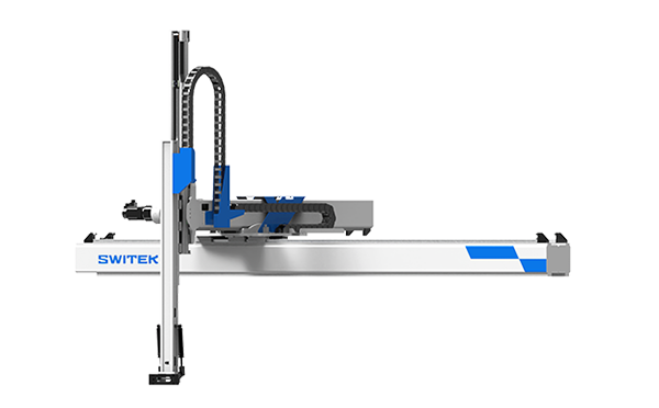
SW7518DS
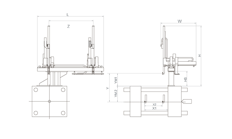
Unit: mm
| X1 | X2 | X3 | X4 | Y | YM1 | YM2 | Z | L | W | H | Payload | 1785 | 1320 | 0 | 0 | 1800 | 500 | 1300 | 3120 | 4160 | 2480 | 2650 | 15kg |
|---|
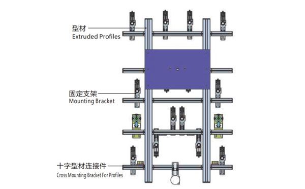
EOAT Assembly Demonstration -- Two Cavities Non-woven Fabric In Mold Insertion
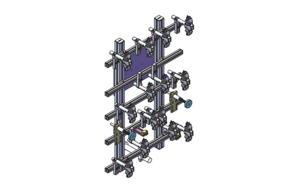
Product Descriptions
Bom List
| Product Name | PN # | Model | Quantity |
|---|---|---|---|
| Extruded Profiles | 4.Y00052 | PEP4040-1000 | 2 |
| Plugs for Profile | 4.Y00072 | PEP4040 | 4 |
| Extruded Profiles | 4.Y000481 | PEP2525-1500 | 2 |
| Extruded Profiles | 4.Y00481 | PEP2525-1000 | 1 |
| Plugs for Profile | 4.Y00070 | PEP2525 | 10 |
| Cross Mounting Bracket for Profiles | 7.Y00356-T | SMBA-2540T | 10 |
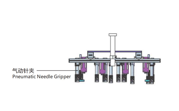
| Pneumatic Needle Gripper | 8.Y00025 | GN2010 | 14 |
| Mounting Bracket | 7.Y00308-T | SMBE2-2060T | 14 |
| Mounting Bracket | 7.Y00309-T | SMBE2-3060T | 1 |
Why is SWITEK SW6715DS Regarded the Best Injection Robot for Welltec 530SEIII Servo Injection Moulding Machine?


