sales06@switek.biz

+86 186 5927 5869

Shopping

Subscrib to Us
sales06@switek.biz
+86 186 5927 5869
Shopping
Subscrib to Us
Keywords:Panasonic A6 Servo Motor, Panasonic A6 Servo Motor Driver, Panasonic A6 Servo Motor setting instruction
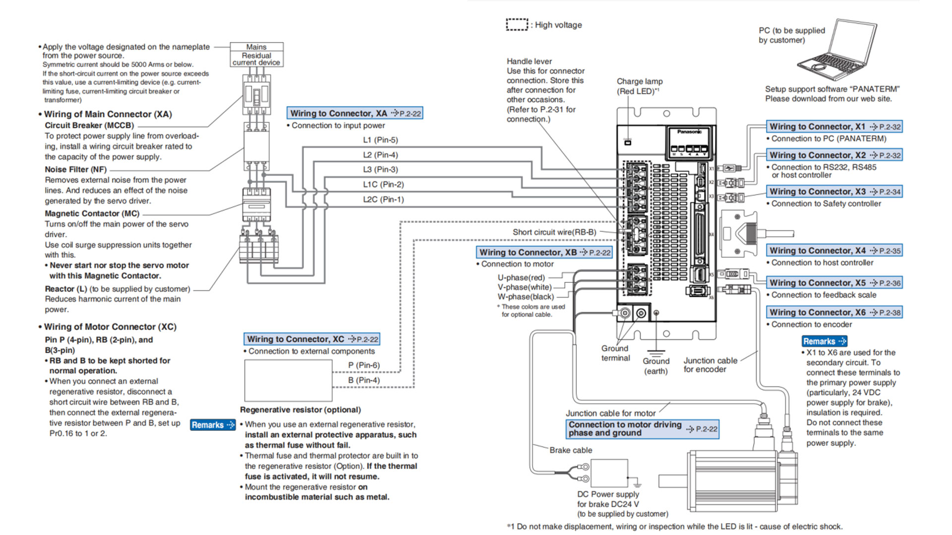
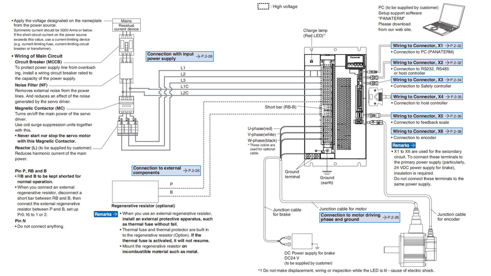
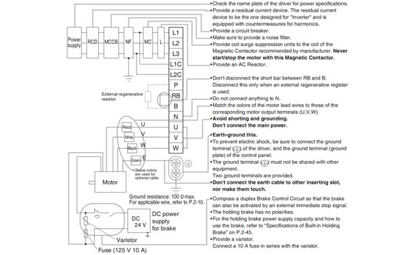
The correct wiring is the guarantee of safety of the Panasonic A6 series AC servo motor application, here in this chapter we'll introduce the correct wiring of the Panasonic A6 AC servo motor and driver in your machineries and automation system.
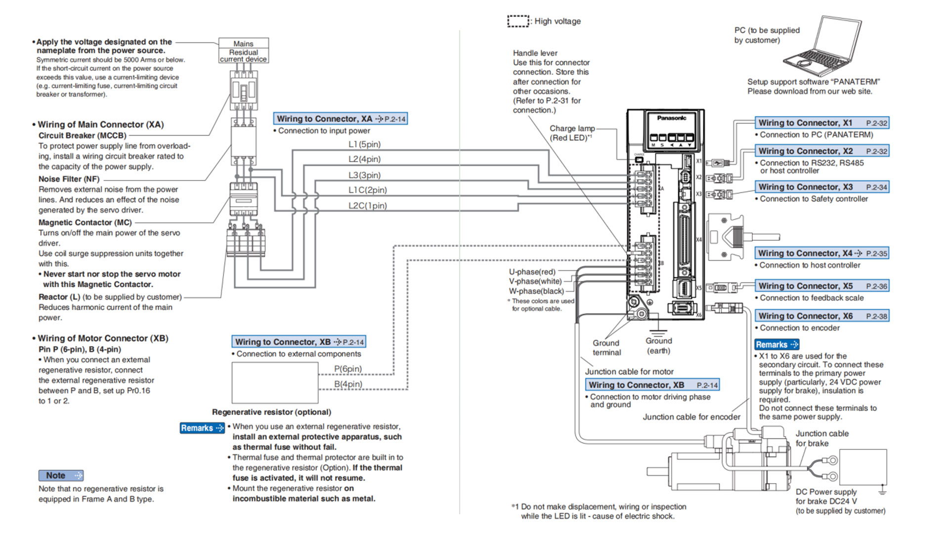
Related page → •P.2-14 "Wiring of the Main Circuit (A to B-frame, 100 V/200 V type)" •P.2-28 "Specifications of Motor connector"
Note → The wiring indicated with the broken line shall be provided only when required.
Related page → •P. 2-28 "Specifications of Motor connector" •P.2-31 "Wiring method to connector" •P.7-132 "Connector kit fo XA" •P.7-133 "Connector kit for XB"
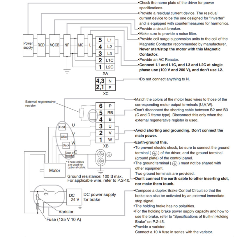
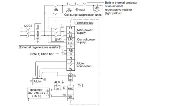
Compose the circuit so that the main circuit power will be shut off when an error occurs. However, if you want to use "immediate stop function" and the main circuit power turns off, please be aware that you will no longer be able to use "immediate stop function".
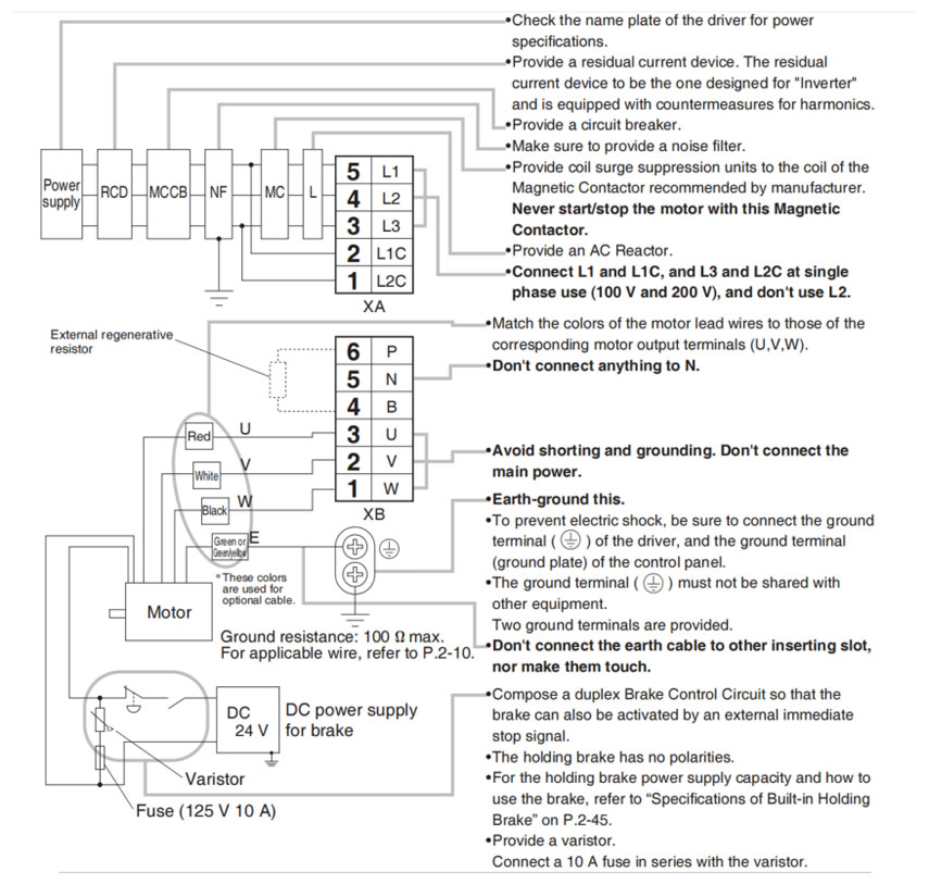
Power supply Single phase, 100 V - 15% to 120 V +10%/200V - 15% to 240V + 10%
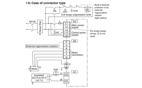
Power supply 3-phase, 200 V - 15% to 240V + 10%
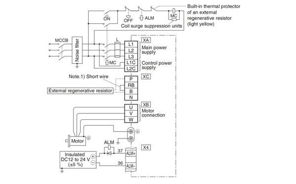
Note.1)
| Frame No. | Short wire (Accessory) | Built-in regenerative resistor | Connection of the connector XB | |
| In case of using an external regenerative resistor. | In case of not using an external regenerative resistor. | |||
| A-frame B-frame | without | without | • Connect an external regenerative resistor between P-B | •Always open between P-B |
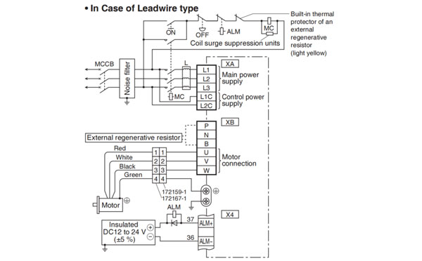
Note → The wiring indicated with the broken line whall be provided only when required.
Related page → •P.2-28 "Specifications of Motor connector" •P.2-31 "Wiring method to connector"
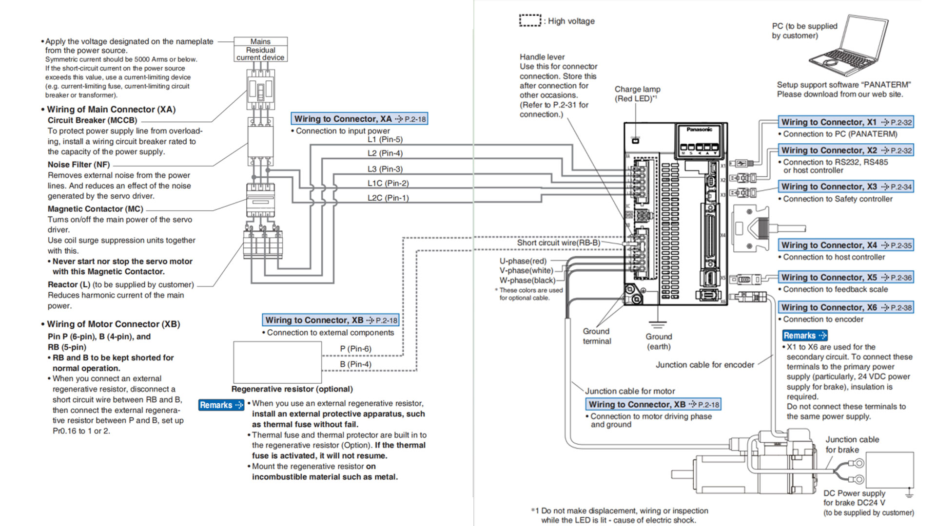
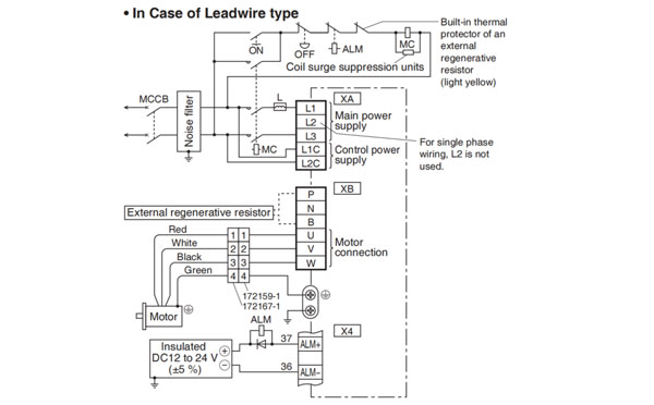
Note → This overall wiring diagram is a typical one. The pages that follow show wiring for specific application. The wiring indicated with the broken line shall be provided only when required.
Related page → •P.7-108 ..."Options" •P.2-18 "Wiring of the Main Circuit (A to B-frame, 100 V/200 V type)" •P. 2-28 " Specifications of Motor connector"
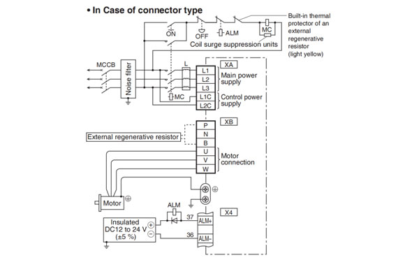
Note → The wiring indicated with the broken line shall be provided only when required.
Related page → •P.2-28 "Specifications of Motor connector" •P.2-31 "Wiring method to connector" •P.7-132 "Connector kit for XA" •P.7-133 "Connector kit for XB"
Note → This overall wiring diagram is a typical one. The pages that follow show wiring for specific application. The wiring indicated with the broken line shall be provided only when required.
Related page → •P.7-108... "Options" •P.2-18 "Wiring of the Main Circuit (E-frame, 200V type)" •P.2-28 "Specifications of Motor connector"
Note → The wiring indicated with the broken line shall be provided only when required.
Related page → •P.2-28 "Specifications of Motor connector" •P.2-31 "Wiring method to connector" •P.7-132 "Connector kit for XA, XC" •P.7-133 "Connector kit for XB"
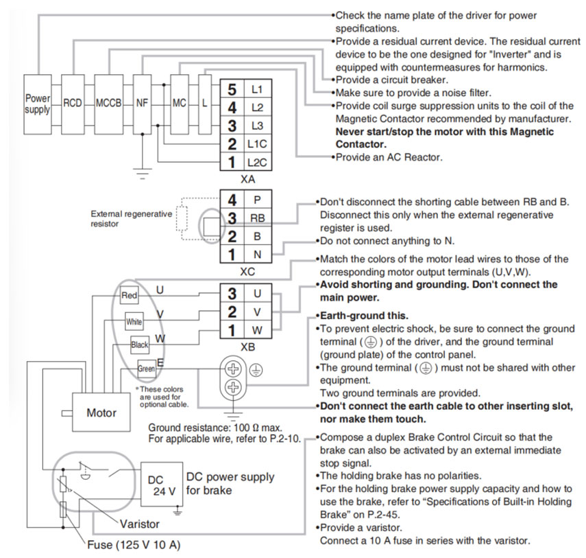
Compose the circuit so that the main circuit power will be shut off when an error occurs. However, if you want to us "immediate stop function" and the main circuit power turns off, please be aware that you will no longer be able tous "immediate stop function".
Power supply 3-phase, 200V -15 % to 240V +10%
Note.1)
| Frame No. | Short wire (Accessory) | Built-in regenerative resistor | Connection of the connector XC | |
| In case of using an external regenerative resistor. | In case of not using an external regenerative resistor. | |||
| E-frame | with | with |
|
|
Note → The wiring indicated with the broken line shall be provided only when required.
Relalted page → &bullP.2-28 "Specifications of Motor connector" •P.2-31 "Wiring method to connector"
Note → This overall wiring diagrma is a typeical one. The pages that follow show wiring for specific application. The wiring indicated with the broken line shall be provided only when required.
Related page → •P.7-108... "Options" •P.2-26 "Wiring of the Main Circuit (F-frame, 200 V type)" •P.2-28 "Specifications of Motor connector"
Note → The wiring indicated with the broken line shall be provided only when required.
Related page → •P.2-28 "Specifications of Motor connector"
Compose the circuit so that the main circuit power will be shut off when an error occurs. However, if you want to use "immediate stop function" andd the main circuit power turns off, please be aware that you will no longer be able to use "immediate stop function".
Power supply 3-phase, 200 V -15% to 230 V +10%
Note.1)
| Frame No. | Short bar (Accessory) | Built-in regenerative resistor | Connection of terminal block | |
| In case of using an external regenerative resistor. | In case of not using an external regenerative resistor. | |||
| F-frame | with | with |
|
|
Note → The wiring indicated with the broken line shall be provided only when required.
Related page → •P.2-28 "Specifications of Motor connector"
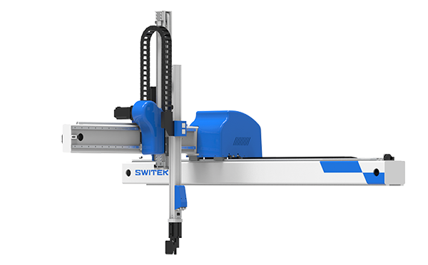
SW6712DS-20
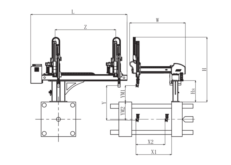
Unit: mm
| X1 | X2 | X3 | X4 | Y | YM1 | YM2 | Z | L | W | H | Payload | 1025 | 840 | 0 | 0 | 1200 | 475 | 725 | 2000 | 3020 | 1610 | 2050 | 8kg |
|---|
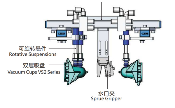
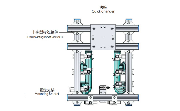
EOAT Assembly Demonstration -- Two Cavities Parts Picking EOAT with Runner Gripping
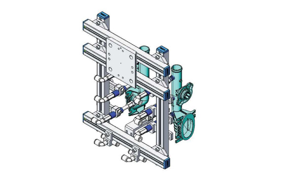
Product Descriptions
Bom List
| Product Name | PN # | Model | Quantity |
|---|---|---|---|
| Quick Changer | 7.Y00175 | QCS-G100 | 1 |
| Sprue Gripper | 8.Y00050 | GR12-12CP | 1 |
| Plugs for Profile | 4.Y00069 | PEP2518 | 10 |
| Cross Mounting Bracket for Profiles | 7.Y00194 | SMBA-2525T | 6 |
| Extruded Profile | 4.Y00455 | PEP2518-1000 | 2 |
| Vacuum Cups VS2 Series | 1.Y03085 | VS2-SA11 | 6 |
| Vacuum Cup Fitting | 7.Y00703 | VM-02-G18 | 6 |
| Rotative Suspensions | 8.Y00061 | VFR1421-G18 | 6 |
| Mounting Bracket | 7.Y00200 | SMBE1-1440T | 6 |
| Connector | 1.Y02510 | APF-M5 | 2 |
| Side Manifold Block | 7.Y00157 | SMB-06M5 | 2 |
| L-Type Threaded HOse Fitting | 1.Y02722 | APL6-01 | 8 |
| Straight Threaded Hose Fitting | 1.Y02725 | APC6-01 | 6 |
For Small and Medium Sized IML Container Producer, Is it Possible to Produce More the One Products with the Same IML Robot?
For manay small and medium sized producer of IML containers it many not be easy to make a decision if to accept the order or not because of the small quantity at the beginning but a huge potential in the future. As the IML robot is a custom made system according to the mold design and the injection molding machine for this mold. But is there any possibility to have one IML robot for a couple of molds? The answer is yes.
The SW8 series of side entry IML robot is one of which an ideal choice for the small and medium sized producer of IML containers. With exchangeable magazine and stacking unit, the IML robot enable the IML containers producers to produce the small and medium sized IML containers and IML lids by the injection molding machine and the IML robot with simply to have the magazine and EOAT replaced for the new mold. But with this IML robot, how will the IML containers produce to achieve the maximized productivity?
To maximized the productivity of the IML system, the key would be to have the injection molding machines and the IML robots well organized according to the products. To make the change the magazine and EOATs faster, we can have the containers with wraping labeling produced in one IML system and have the 3/5 face labeling containers and the lids produced by another IML system. It's not recommended to have the containers with wraping labeling to be produced by the same IML system with an IML lids, which will need to change both the Magazine and the stacking unit and the time to start the system up would be much longer.
For more advisory of an IML project planning please feel free to contact Adams from SWITEK Automation, your personal consultant of IML system integration.