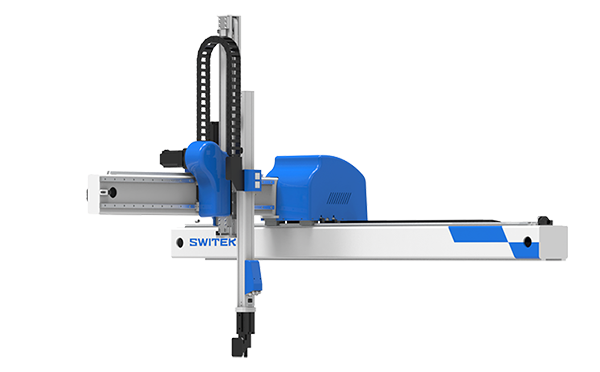
With the control system developed by the Austria automatic company SIGMATEK GmbH & Co KG, SWITEK high speed side entry IML robot is providing a more efficient and outstanding performance for your quality bulk production of the IML Yogurt Cups.
1.3 Function Screen
1.3.16 Variables
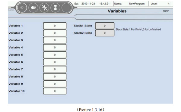
At the Function screen, select the Variables button to enter this page, as the picture below 1.3.16;
There are ten variables you can use in a Teaching program, can be used for signs, statistics, etc. Another multiple vacuum, input, output signal monitoring.
At the same time the user can click on an empty area behind the variable renaming variables, facilitate the teaching mode identification of variables;
Stack state: 1 means stack is finish, 0 is not finish.
1.3.17 Axis Configuration
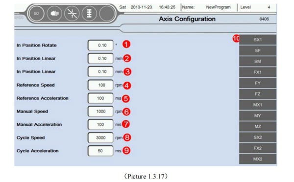
Select the Back button return to the menu interface, Choose Axis Configuration button into this page, as the picture below 1.3.17:
In position Rotate: If the unit is running servo axis angle, determine the minimum angle of deviation is in place. For example, if you want to rotate 30°, here is set to 0.10°, then when the servo to 29.9°, system default that has been in place. The remaining 0.1° with the next step to run together;
In position Linear: Running unit is mm, determine whether the minimum position deviation in place. For example: If you want to move a 30mm, this set is 0.10mm, then, when the servo to 29.90mm. System default that has been in place. The remaining 0.1mm with the next step to run together;
In position Linear: Running unit is mm, determine whether the minimum position deviation in place. For example: If you want to move a 30mm. This set is 0.10mm, then, when the servo to 29.90mm. System Default that has been in place. The remaining 0.1mm with the next step to run together; Attention: This place interval and teaching program in place each icon editing interface consistent intervals. The default value of the program between the two major party in place interval setting.
Reference Speed: Return to the Home when the macimum speed of the motor. Unit is RPM (r/min)
Reference Acceleration: Return to the HOme when the acceleration of the motor.Unit is ms (millisecond). Attention, the shorter the accelelration time acceleration is bigger.
Manual speed: Manual mode the maximum run speed of the motor. Unit is RPM (r/min).
Manual Acceleration: Manual mode the maximum run acceleration of the motor. Unit is ms (millisecond). Attention, the shorter the acceleration time acceleration is bigger.
Cycle Speed: Automatic mode maximum running speed of the motor. Unit is RPM (r/min)
Cycle Acceleration: The acceleration of time can't more than the set value when run automatically. Attention: Of the speed/acceleration limiting, servo motor running parameters Settings interface with maximum revolutions. Program defaults to the smaller one between the two values is the highes speed.
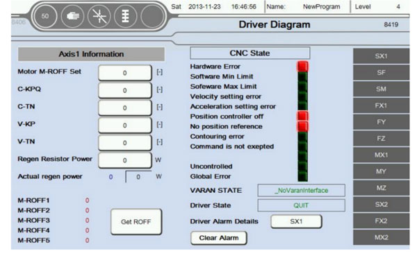
Servo axis status information: Can click on the following Click "SX", Enter the current picture, as the picture below 1.3.18;
Information in a servo axis parameters to automatically read. Don't need to be set. Suggested that only when the default parameters inapplicable, to modify carefully. Attention:
When all the parameters to 0 before restart automatically read the system default parameters (Mainly used in the case of parameter change chaos, other situations without modification). If these parameters are not very accurate, can be set automatically according to the actual running situation of motor. Such that the zero angle of motor is not accurate, can click on the button get zero. Then write into motor M-ROFF setting;
When ** axis is pulse type servo, you don't need to set up and read the parameter information and status. CNC Status Hardward Error: Servo drive hardware error; Softward Min Limit: Axis is beyond of software minimum position setting (Servo operation parameters settings); Software Max Limit: Axis is beyond of software maximum position setting (Servo operation parameters settings); Velocity Setting Error: Actual speed exceeds the speed of the motor setting; Acceleration Setting Error: Actual Acceleration exceeds the Acceleration of the motor setting; Position controller off: Close enable or position control; No position reference: Didn't finish the reference action; Contouring error: Axis actual position beyond set deviation; Command error: The instructions are not allowed to perform; Idle position: Actual position error, idle position; Uncontrolled: Can't control the action; Other error:
Best Buy Robotic Arm for Injection Molding Machine
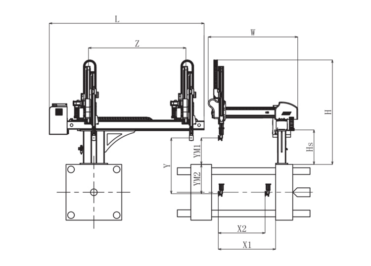
SW6712DS-20
Unit: mm
X1
X2
X3
X4
Y
YM1
YM2
Z
L
W
H
Payload
1025
840
0
0
1200
475
725
2000
3020
1610
2050
8kg
The Application of End of Robotic Arm Tooling
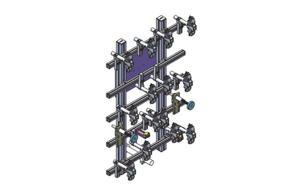
EOAT Assembly Demonstration -- Two Cavities Non-woven Fabric In Mold Insertion
Two Cavities Non-woven Fabrics In Mold Insertion EOAT Design
Product Descriptions
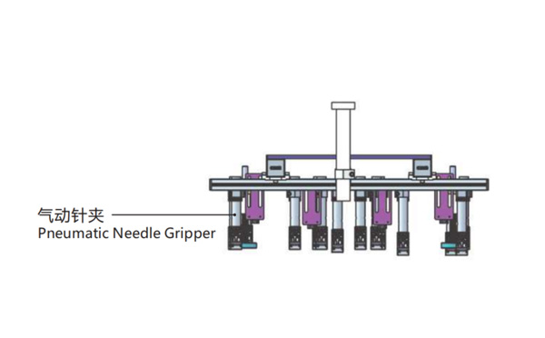
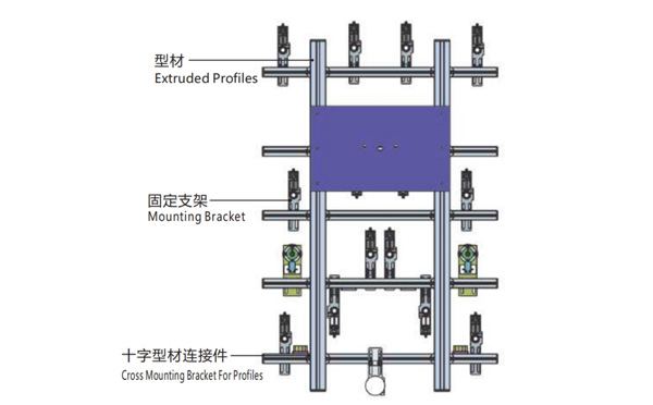
This EOAT is for 2 Cavities Non-woven Fabric In Mold Insertion;
The Inserts (Non-woven Fabric) Would be Take Out or Embeded by Pneumatic Needle Gripper;
The Grippers Would be Drived by Two Air-Routes, One for Each Cavity;
The Gross Weight of the EOAT Seet is about 7kg.
Bom List
Product Name
PN #
Model
Quantity
Extruded Profiles
4.Y00052
PEP4040-1000
2
Plugs for Profile
4.Y00072
PEP4040
4
Extruded Profiles
4.Y000481
PEP2525-1500
2
Extruded Profiles
4.Y00481
PEP2525-1000
1
Plugs for Profile
4.Y00070
PEP2525
10
Cross Mounting Bracket for Profiles
7.Y00356-T
SMBA-2540T
10
Pneumatic Needle Gripper
8.Y00025
GN2010
14
Mounting Bracket
7.Y00308-T
SMBE2-2060T
14
Mounting Bracket
7.Y00309-T
SMBE2-3060T
1
Q & A About Robotic Arms and Injection Automation
YIZUMI P350 or P380K3, which one would be a better choice for your IML project?
P350 is a high speed injection molding machine designed for thin-wall containers while P380K3 is the third generation of high speed injection molding machine by YIZUMI designed for thin-wall containers. With 30 Tons more in clamping force, does it mean that P380K3 will compatible to the molds designed according to the parameters of P350?
In one just finished IML project we encountered something embrassing. There's one mold designed according to the parameter of YIZUMI P350, and we have a P380K3 in our system testing workshop, but when the mold received we find that the mold thinkness exceeded the max mold thickness of the P380K3. After double check the parameters of both the injection molding machine we found that Mold thickness allowed for P350 is 300~750mm while the mold thickness for P380K3 is only 250~650mm. And the Max Daylight of P380K3 is 160mm less than P350.
Then how to choose between, which one would be a better choice for your IML project? It would be depends on the size of the parts of which you're producing. For smaller container 30 Tons more clamping force with 160mm less max daylight means that the injection molding machine will have a less mold Open/Close time and result in a higher productivity while for larger size containers P350 will allow you to install a thicker mold, it would be more friendly to an IML project of deep cavity containers.
For more insights of the cutting edge IML technology please feel free to contact Adams from SWITEK, your personal consultant of IML Solutions.