
sales06@switek.biz

+86 186 5927 5869

Shopping

Subscrib to Us
sales06@switek.biz
+86 186 5927 5869
Shopping
Subscrib to Us
Keywords:Panasonic A6 Servo Installation Instruction, Panasonic A6 Driver, Panasonic A6 Series Servo Motor Manual
The torque control is performed according to the torque command specified in the form of analog voltage. For controlling the torque, the speed limit input is required in addition to the torque command to maintain the motor speed within the speed limit.
With the A5 series, 3 torque control modes are available, each requires different torque command and speed limit as shown in the table below.
• Pr3.17 (Selection of torque command)
| Parameter | Title | Torque command input | Velocity limit input |
|---|---|---|---|
| 0 | Selection of torque command 1 | Analog input 1*1 (Al1, 16-bit resolution) | Parameter value (Pr3.21) |
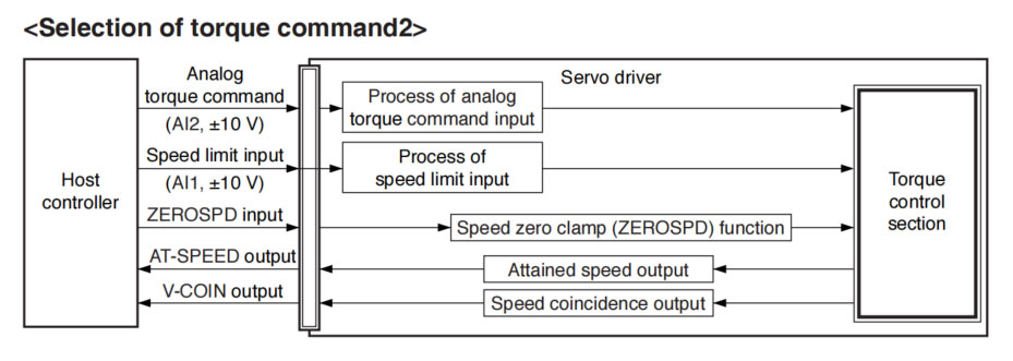
| 1 | Selection of torque command 2 | Analog input 2 (Al2, 12-bit resolution) | Analog input 1 (Al1, 16-bit resolution) |
| 2 | Selection of torque command 3 | Analog input 1 *1 (Al1, 16-bit resolution) | Parameter value (Pr3.21, Pr3.22) |
*1 For Pr0.01 Control mode setup = 5 (velocity/torque control), the torque command input is the analog input 2 (Al2, 12-bit resolution).
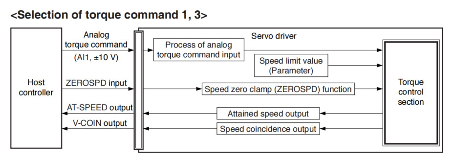
This process converts the analog torque command input (voltage) to the equivalent digital torque command having the same effect. You can set the filter or adjust the offset to eliminate noise.
• Relevant parameters <Selection of torque command 1, 3>
| Parameter No. | Title | Range | Unit | Function |
|---|---|---|---|---|
| Pr3.18 | Torque command direction selection | 0 to 1 | — | Select the direction positive/negative direction of torque command. |
| Pr3.19 | Torque command | 10 to 100 | 0.1 V/100 % | Based on the voltage (V) applied to the analog torque command (TRQ R), set up the conversion gain to torque command (%). |
| Pr3.20 | Input reversal of torque command | 0 to 1 | — | Set up the polarity of the voltage applied to the analog torque command (TRQR). |
| Pr4.22 | Analog input 1 (Al1) offset setup | -5578 to 5578 | 0.359 mV | Set up the offset correction value applied to the voltage fed to the analog input 1. |
| Pr4.23 | Analog input 1 (Al1) filter | 0 to 6400 | 0.01 ms | Set up the time constant of 1st delay filter that determines the lag time behind the voltage applied to the analog input 1. |
• Relevant parameters <Selection of torque command 2>
| Parameter No. | Title | Range | Unit | Function |
|---|---|---|---|---|
| Pr3.18 | Torque command direction selection | 0 to 1 | — | Select the direction positive/negative direction of torque command. |
| Pr3.19 | Input gain of torque command | 10 to 100 | 0.1 V/100 % | Based on the voltage (V) applied to the analog torque command (TRQ R), set up the vonversion gain to torque command (%). |
| Pr3.20 | Input reversal of torque command | 0 to 1 | — | Set up the polarity of the voltage applied to the analog torque command (TRQR). |
| Pr4.25 | Analog input 2 (Al2) offset setup | -342 to 342 | 5.86 mV | Set up the offset correction value applied to the voltage fed to the analog input 2. |
| Pr4.26 | Analog input 2 (Al2) filter | 0 to 6400 | 0.01 ms | Set up the time constant of 1st delay filter that determines the lag time behind the voltage applied to the analog input 2. |
The speed limit is one of protective functions used during torque control. This function regulates the motor speed so that it does not exceed the speed limit while the torque is controlled.
• Relevant parameters <Selection of torque command 1, 3>
| Parameter No. | Title | Range | Unit | Function |
|---|---|---|---|---|
| Pr3.21 | Speed limit value 1 | 0 to 20000 | r/min | Set the speed limit used for torque controlling. |
| Pr3.22 | Speed limit value 2 | 0 to 20000 | r/min | |
| Pr3.15 | Speed zero-clamp function selection | 0 to 3 | — | You can set up the function of the speed zero clamp input. |
• Relevant parameters <Selection of torque command 2>
| Parameter No. | Title | Range | Unit | Function |
|---|---|---|---|---|
| Pr3.02 | Input gain of speed command | 10 to 2000 | (r/min) /V | Based on the voltage applied to the analog speed command (SPR), set up the conversion gain to motor command speed. |
| Pr4.22 | Analog input 1 (Al 1) offset setup | -5578 to 5578 | 0.359 mV | Set up the offset correction value applied to the voltage fed to the analog input 1. |
| Pr4.23 | Analog input 1 (Al1) filter | 0 to 6400 | 0.01 ms | Set up the time constant of 1st delay filter that determines the lag time behind the voltage applied to the analog input 1. |
| Pr3.15 | Speed zero-clamp function selection | 0 to 3 | — | You can set up the function of the speed zero clamp input. |
SW6308DS-20
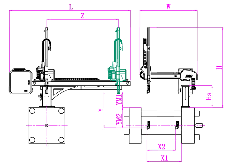
Unit: mm
| X1 | X2 | X3 | X4 | Y | YM1 | YM2 | Z | L | W | H | Payload | 740 | 800 | 0 | 0 | 800 | 235 | 565 | 1350 | 2320 | 1500 | 1460 | 3kg |
|---|
EOAT Assembly Demonstration -- One Cavity Instrument Panel Picking EOAT
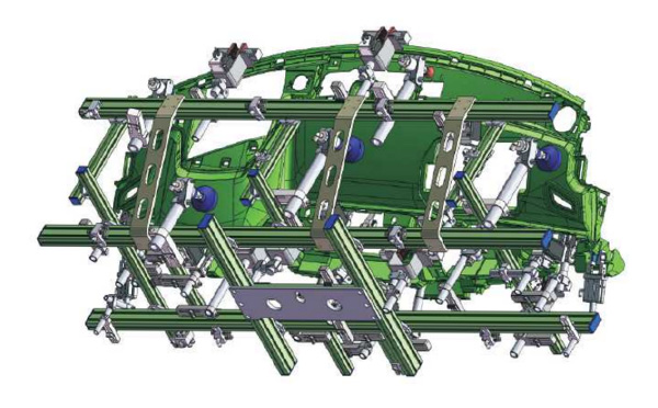
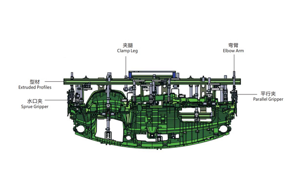
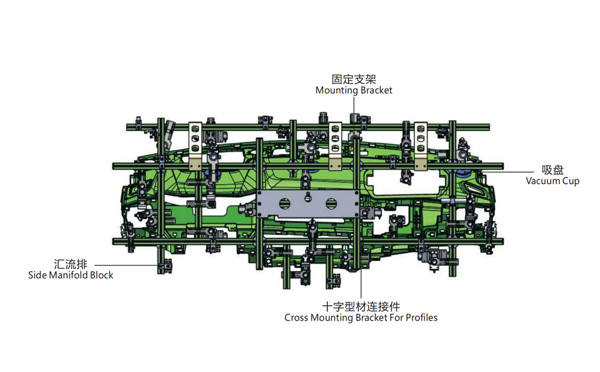
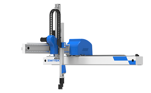
Product Descriptions
Why There's An Additional Static Charge Ring Installed to Some IML System?
For visitors of SWITEKK website will find that for the IML system no matter if it's side entry IML robot or Top Entry IML Robot, you can see a ring just outside the mold area in some of the IML system but not to the other IML system. Why would it happen and what's the function of this ring to the IML system?
The ring installed is a static charging ring. For a better understanding of the function of this static charging ring we'll need to know the types of the labels which we're using in an IML project. For an IML container made from PP (Polypropylene) there're two main types of IML labels, the regular material IML labels which could be easily static charged from the inner side of the label and the metallic label of which has a metallic layer will releas the static immediately. In this case we'll need to have the label static charged from outside of the label. That's why an extra static charging ring is to be installed to the IML system to ensure that the metallic IML label could be well static charged.
For more knowledge about IML and IML solutions just follow up https://www.gechiml.com for the up to date solutions of IML from SWITEK automation and contact Adams for a turn-key solutions of IML.


