sales06@switek.biz

+86 186 5927 5869

Shopping

Subscrib to Us
sales06@switek.biz
+86 186 5927 5869
Shopping
Subscrib to Us
Keywords:Panasonic A6 Servo Installation Instruction, Panasonic A6 Driver, Panasonic A6 Series Servo Motor Manual
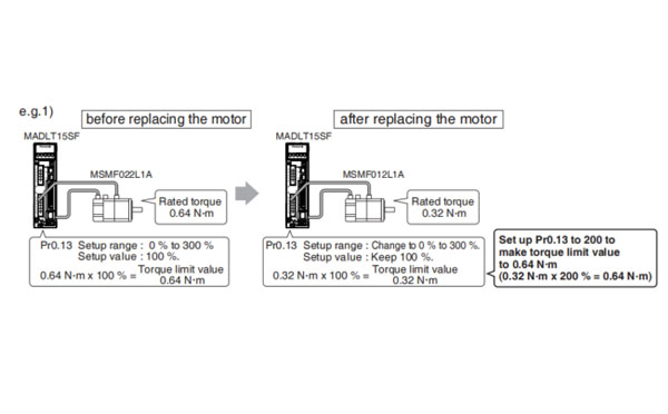
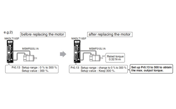
Torque limit setup range is 0 to 300 and default is 300 except the combinations of the motor and the driver listed in the table below.
| Frame | Model No. | Applicable motor | Max. value of torque limit |
|---|---|---|---|
| A | MADL☐01☐☐ | MHMF5AZL1☐☐ | 350 |
| MADL☐11☐☐ | MQMF011L1☐☐ | 350 | |
| MHMF011L1☐☐ | 350 | ||
| MADL☐05☐☐ | MHMF5AZL1☐☐ | 350 | |
| MQMF012L2☐☐ | 350 | ||
| MHMF012L1☐☐ | 350 | ||
| MADL☐15☐☐ | MQMF022L1☐☐ | 350 | |
| MHMF022L1☐☐ | 350 | ||
| B | MBDL☐21☐☐ | MQMF021L1☐☐ | 350 |
| MHMF021L1☐☐ | 350 | ||
| MBDL☐25☐☐ | MQMF042L1☐☐ | 350 | |
| MHMF042L1☐☐ | 350 | ||
| C | MCDL☐31☐☐ | MQMF041L1☐☐ | 350 |
| MHMF041L1☐☐ | 350 | ||
| MCDL☐35☐☐ | MHMF082L1☐☐ | 350 | |
| D | MDDL☐45☐☐ | MGMF092L1☐☐ | 350 |
| MDDL☐55☐☐ | MHMF092L1☐☐ | 350 | |
| MGMF132L1☐☐ | 281 | ||
| E | MEDL☐83☐☐ | MGMF182L1☐☐ | 251 |
| MEDL☐93☐☐ | MGMF242L1☐☐ | 296 | |
| F | MFDL☐B3☐☐ | MGMF292L1☐☐ | 245 |
| MGMF442L1☐☐ | 250 |
Caution → • The above limit applies to Pr0.13 (1st torque limit), Pr5.22 (2nd torque limit), Pr5.11
(Torque setup for emergency stop), Pr5.25 (External input positive direction torque limit) and Pr5.26 (Exernal input negative direction
torque limit).
When you change the motor model, above max. value may change as well. Check and reset the setup values of Pr0.13, Pr5.22, Pr5.11, Pr5.25 and Pr5.26.
As stated previously, torque limit setup range might change when you replace the combination of the motor and the driver. Pay attention to the followings.
Please don't use other combination besides the combination of designation.
For details of combination refer to P.1-19 "4. Check of the Combination of the Driver and the Motor".

SW6310S-20
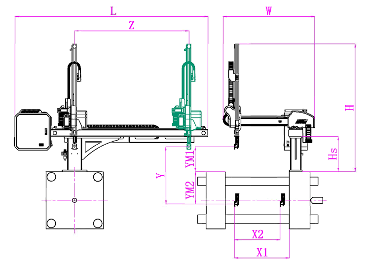
Unit: mm
| X1 | X2 | X3 | X4 | Y | YM1 | YM2 | Z | L | W | H | Payload | 980 | 820 | 0 | 0 | 1000 | 235 | 765 | 1580 | 2640 | 1500 | 1930 | 3kg |
|---|
EOAT Assembly Demonstration -- One Cavity Car Bumper Picking EOAT
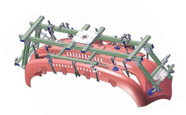
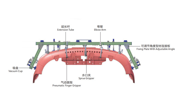
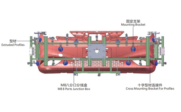
Product Descriptions
For a Bucket Injection Production System with Haitian Jupiter Series Two Platens Injection Molding Machine, which Robot is the Best for It?
JU4500 is a medium sized two platen hydraulic injection molding machine by Haitian group with a clampling force of 4500kN. As a two platen injection molding machine it has a much shorter body length and is an ideal choice for the production of deep cavity products such as buckets etc., below is the general parameters of it:
For a bucket production project with JU4500 we have two recommendation, one is for the production of the plain bucket which the robot will do the picking and stacking only, the robot to recommend is SWITEK 3 axis servo injection robot SW6712DS-20 which has a payload of 6kg and is an ideal choice for the picking and stacking of the buckets; the other is a bcket production project with IML, which the robot will not only pick and stacking the bucket but also have the label put into the mold, the robot to recommend is SWITEK SW7312DS, with kick-back design, it'll will provide more space for the EOAT.
For more information about robot selection for Haitian injection molding machine please contact Adams from SWITEK to get a professional advisory of robot selection for your injection automation solutions.