
sales06@switek.biz

+86 186 5927 5869

Shopping

Subscrib to Us
sales06@switek.biz
+86 186 5927 5869
Shopping
Subscrib to Us
Keywords:Panasonic A6 Servo Motor, Panasonic A6 Servo Motor Driver, Panasonic A6 Servo Motor setting instruction
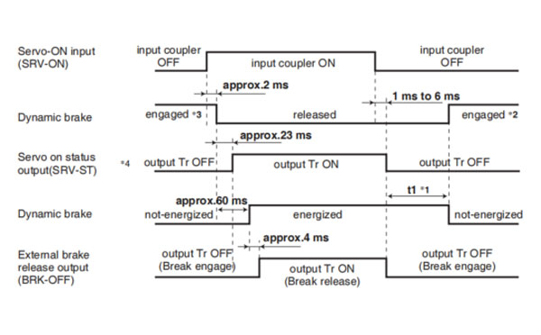
The timing chart shows the servo-on signal accept timing on power-up of a Panasonic A6 series AC servo motor from AC power-ON to command input.
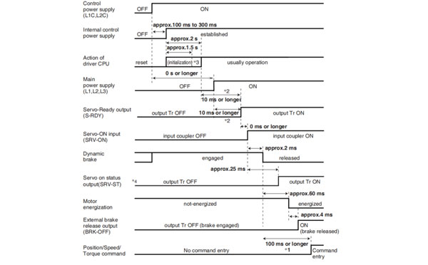
Caution → *1. In this term Servo-ON input (SRV-ON) turns ON as a hard ware, but operation command can not be received.
*2. S-RDY output will turn on when both conditionss are met, initialization of micro computer has been completed and the main power has been turned on.
*3. After internal control power supply, protective functions are active from approx. 1.5 sec after the start of initializing microcomputer. Please set the signals, especially for protective function, for example over-travel inhibit input (POT, NOT) or external scale input, so as to decide their logic unit this term.
The lapse time can be changed with Pr6.18 Wait time after power-up.
*4. Servo ON status output (SRV-ST) is a signal indicating that it has received the Servo-On input; please note that it is not an indication showing command input is possible.
Related page → •P.4-6 to P.4-85... "Details of parameter"
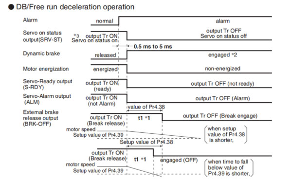
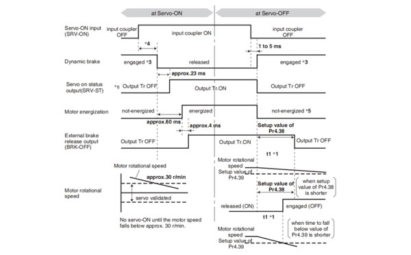
• DB/Free run deceleration operation
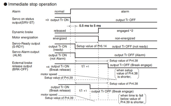
• Immediate stop operation
Caution → *1. t1 will be a shorter time of either the setup value of Pr4.38[Mechanical brake action at running setup] or elapsing time for the motor speed to fall below Pr4.39 [Brake release speed setup].
t1 will be 0 when the motor is in stall regardless of the setup pf Pr4.37.
*2. When an alarm is generated, the dynamic brake operates according to Pr5.10 Sequence at alarm.
*3. Servo ON status output (SRV-ST) is a signal indicating that it has received the Servo-On input; please note that it is not an indication showing command input is possible.
*4. The setting where Pr4.38 "Mechanical braking setting during operation" = Pr6.14 "Immediate stop time in case of alarm" is recommended.
When set to Pr4.38 ≤ Pr6.14, the brake will be operated after lapse of Pr4.38 time.
When set to Pr4.38 < Pr6.14, the brake will not operate even after lapse of Pr4.38 time, but will operate when transitioned to OFF state.
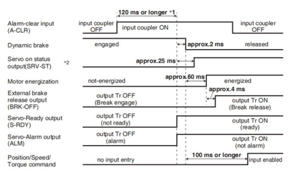
Caution → *1. The alarm clear input recognition time can be changed in Pr5.16 Alarm clear input setup.
*2. Servo ON status output (SRV-ST) is a signal indicating that it has received the Servo-On input; please note that it is not an indication showing command input is possible.
Remarks → To turn on/off the servo during normal operation, first stop the motor.
Caution → *1. t1 depends on the setup value of Pr4.37 Setup of mechanical brake action at stalling.
*2. The operation of dynamic brake during servo off depends on the setup value of Pr5.06 Sequence at servo off.
*3. Servo-ON will not be activated until the motor speed falls below approx.30 r/min.
*4. Servo ON status output (SRV-ST) is a signal indicating that it has received the Servo-On input; please note that it is not an indication showing command input is possible.
Related page → •P.4-47, 4-54 "Details of Parameter"
Remarks → Timing at emergency stop or trip. Do not repeat this sequence.
Caution → *1. t1 will be a shorter time of either the setup value of Pr4.38 "Mechanical brake action at running setup" or elapsing for the motor speed to fall below Pr4.39 "Brake release speed setup".
*2. Even though the SRV-ON signal is turned on again during the motor deceleration, Servo-ON will not be activated until the motor stops.
*3. For the action of dynamic brake at alarm occurrence, refer to an explanation of Pr5.06, "Sequence at Servo-OFF" as well.
*4. Servo-ON will not be activated until the motor speed falls below approx. 30r/min.
*5. For the motor energization during deceleration at Servo-OFF depends on the setup value of Pr.5.08, "Sequence at Servo-OFF".
*6. Servo ON status output (SRV-ST) is a signal indicating that it has received the Servo-On input; please not that it is not an indication showing command input is possible.
Related page → • P.2-47 "Dynamic brake"
SW6712DS-20
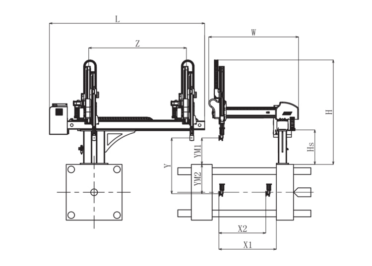
Unit: mm
| X1 | X2 | X3 | X4 | Y | YM1 | YM2 | Z | L | W | H | Payload | 1025 | 840 | 0 | 0 | 1200 | 475 | 725 | 2000 | 3020 | 1610 | 2050 | 8kg |
|---|
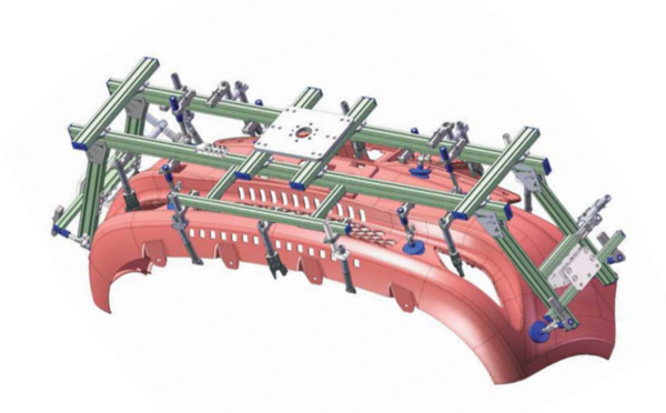
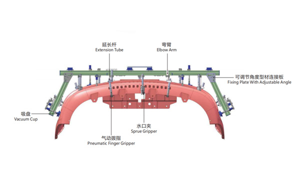
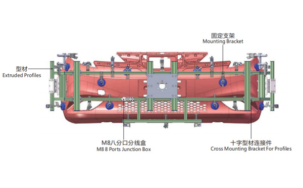
EOAT Assembly Demonstration -- One Cavity Car Bumper Picking EOAT
Product Descriptions
What's a Smart Factory and How Would a Smart Factory Designed?
With the increasing labour cost globally, more and more injection molding factory owners are looking for solutions of a smart factory. But what would be a smart factory looks like and how to design a smart factory? The newly posted video of Haitian group in their Youtube account is a good reference of what would be a smeart factory.
In the video above we can find something in comman of what a smart factory would be. First of all there's a centralized feeding system from which the material for all the injection molding machines are delivred; In this factory all the parts produced are collected and transported to another workshop via a conveyor. What would be in behind these injection molding machines and conveyors to support the running of the smart factory?
The MES system (Manufacturing Execution System) would be a vital part of a smart factory which will monitor the production process of the parts, just in time mangaement of the machineries, products quality control and resources following up. The samrt factory would be smart solution to help the factory owners to reduce the labour cost.
Although sounds great, but the smart factory is not as suitable for the small and medium size producers whom will change the mould frequently. As an information technology based production, the smart factory is an integration of the software and the hardware. It may be easy to change the parameter of the software, but would be a nightmare to have the hardware changed to match the new system.
Cooperating with LESSO group in building up their smart factory for pipe fittings production, SWITEK is experienced in supply robots with protocol for MES and other smart factory system. For more details about the injection robot for the smart factory sytem, please contact Adams from SWITEK, your personal consultant of injection robot selection.


