sales06@switek.biz

+86 186 5927 5869

Shopping

Subscrib to Us
sales06@switek.biz
+86 186 5927 5869
Shopping
Subscrib to Us
Keywords:Panasonic A6 Servo Motor, Panasonic A6 Servo Motor Driver, Panasonic A6 Servo Motor setting instruction
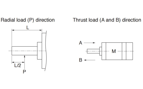
The output shaft is where the Panasonic A6 series of AC servo motor assembled to the reducer. Here in this chapter you'll have a detailed sheet of the permissible load of the Panasonic A6 series of AC Servo motor at output shaft.
Unit: N (1 kgf=9.8N)
| Motor series | Motor output | At assembly | During running | |||
|---|---|---|---|---|---|---|
| Radial thrust | Thrust load | Radial thrust | Thrust load A and B-direction | |||
| A-direction | B-direction | |||||
| MSMF | 50W, 100W | 147 | 88 | 117.6 | 68.6 | 58.8 |
| 200W, 400W | 392 | 147 | 196 | 245 | 98 | |
| 75W, 1.0kW (☐80) | 686 | 294 | 392 | 392 | 147 | |
| 1.0kW(☐100) to 3.0kW | 980 | 588 | 686 | 490 | 196 | |
| 4.0kW, 5.0kW | 784 | 343 | ||||
| MQMF | 100W | 147 | 88 | 117.6 | 68.6 | 58.8 |
| 200W, 400W | 392 | 147 | 196 | 245 | 98 | |
| MDMF | 1.0kW to 2.0kW | 980 | 588 | 686 | 490 | 196 |
| 3.0kW | 784 | 343 | ||||
| 4.0kW, 5.0kW | 1666 | 784 | 980 | |||
| MGMF | 850W to 1.8kW | 980 | 588 | 686 | 686 | 196 |
| 2.4kW | 1666 | 784 | 980 | 1176 | 490 | |
| 2.9kW | ||||||
| 4.4kW | 1470 | |||||
| MHMF | 50W | 147 | 88 | 117.6 | 68.6 | 49 |
| 100W | 58.8 | |||||
| 200W, 400W | 392 | 147 | 196 | 245 | 98 | |
| 750W, 1.0kW (☐80) | 686 | 294 | 392 | 392 | 147 | |
| 1.0kW(☐130), 1.5kW | 980 | 588 | 686 | 490 | 196 | |
| 2.0kW to 5.0kW | 1666 | 784 | 980 | 784 | 343 | |
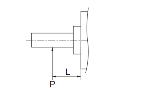
Note → When the load point varies, calculate the permissible radial load, P (N) from the distance of the load point, L (mm) from the mounting flange based on the formula of the right table, and make it smaller than the calculated result.
| Motor series | Motor output | Formula of Load and load point relation |
|---|---|---|
| MSMF | 50W | P=3533/(L+39) |
| 100W | P=4905/(L+59) | |
| 200W | P=14945/(L+46) | |
| 400W | P=19723/(L+66.5) | |
| 750W | P=37044/(L+77) | |
| 1.0kW(☐80) | P=43198/(L+92.7) | |
| 1.0kW(☐100)~3.0kW | P=20090/(L+13.5) | |
| MQMF | 100W | P=3420/(L+28.8) |
| 200W | P=14639/(L+36) | |
| 400W | P=17579/(L+48) | |
| MDMF | 1.0kW~2.0kW | P=19110/(L+11.5) |
| 3.0kW | P=34496/(L+11.5) | |
| 4.0kW, 5.0kW | P=42336/(L+19) |
| Motor Series | Motor output | Formula of Load and load point relation |
|---|---|---|
| MGMF | 850W~1.8kW | P=26754/(L+11.5) |
| 2.4kW | P=63504/(L+19) | |
| 2.9kW | P=63504/(L+19) | |
| 4.4kW | P=79380/(L+19) | |
| MHMF | 50W | P=3240/(L+29) |
| 100W | P=4380/(L+43) | |
| 200W | P=15741/(L+41) | |
| 400W | P=20176/(L+59) | |
| 750W | P=36005/(L+66) | |
| 1.0kW(☐80) | P=41101/(L+79) | |
| 1.0kW(☐130), 1.5kW | P=22785/(L+11.5) | |
| 2.0kW~5.0kW | P=46256/(L+19) |

SW255C
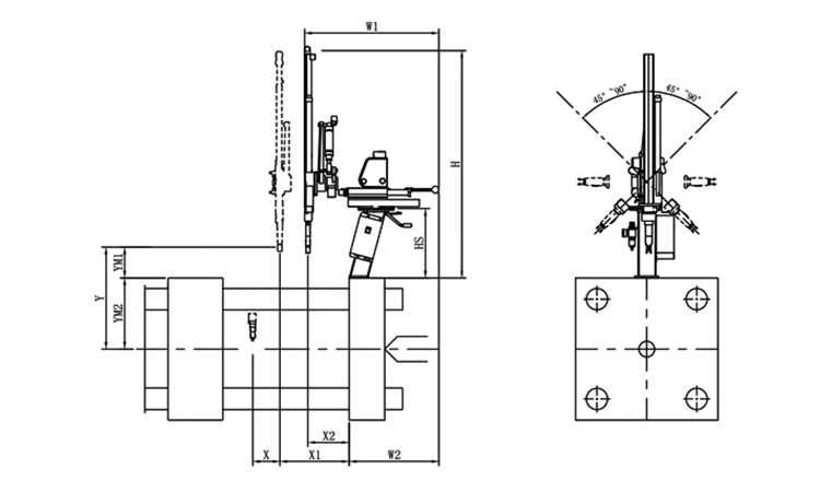
Unit: mm
| X1 | X2 | X3 | X4 | Y | YM1 | YM2 | Z | L | W | H | Payload | 300 | 100 | 0 | 0 | 550 | 155 | 395 | -45°~+45° | 650 | 650 | 1260 | 2kg |
|---|
EOAT Assembly Demonstration -- Two Cavities Non-woven Fabric In Mold Insertion
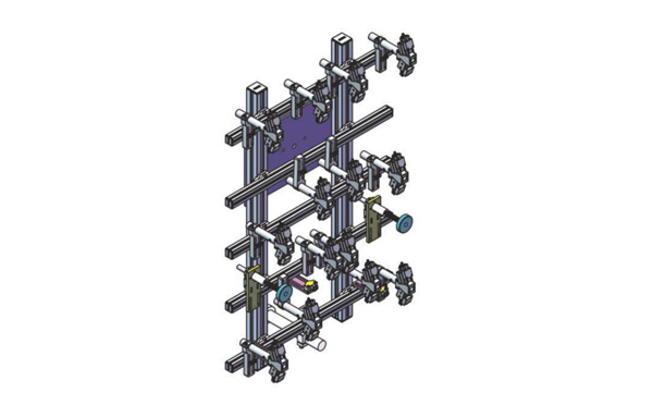
Product Descriptions
Bom List
| Product Name | PN # | Model | Quantity |
|---|---|---|---|
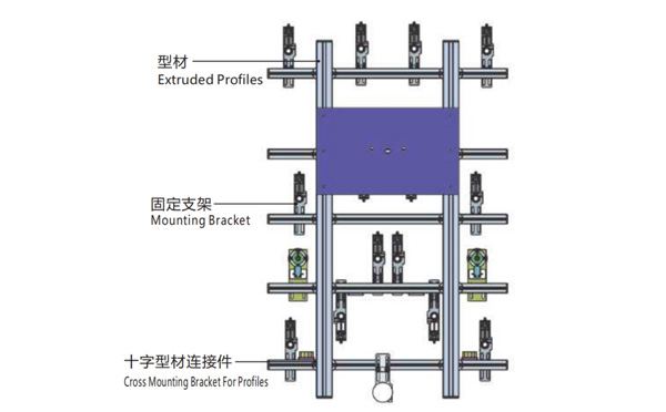
| Extruded Profiles | 4.Y00052 | PEP4040-1000 | 2 |
| Plugs for Profile | 4.Y00072 | PEP4040 | 4 |
| Extruded Profiles | 4.Y000481 | PEP2525-1500 | 2 |
| Extruded Profiles | 4.Y00481 | PEP2525-1000 | 1 |
| Plugs for Profile | 4.Y00070 | PEP2525 | 10 |
| Cross Mounting Bracket for Profiles | 7.Y00356-T | SMBA-2540T | 10 |
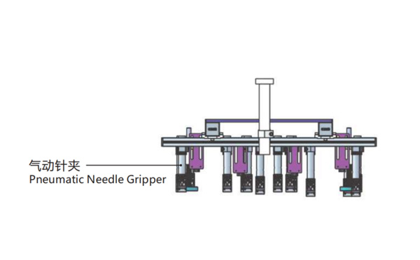
| Pneumatic Needle Gripper | 8.Y00025 | GN2010 | 14 |
| Mounting Bracket | 7.Y00308-T | SMBE2-2060T | 14 |
| Mounting Bracket | 7.Y00309-T | SMBE2-3060T | 1 |
What's the Advantages of SWITEK Side Entry Forks Folding Robot SW818?
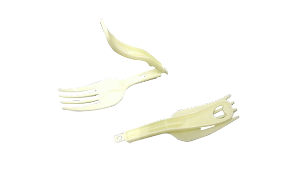
Foldable Forks is a disposable cutlery which was firstly introduced to the Chinese people with the instant noodle in year 1992. At that time the production of the foldable forks are still a high technology with the mold making technology controlled by the mold makers from outside China. The "Instant noodle" was still something luxiliary in China at that time.
The first SWITEK side entry 64 cavities forks pick and folding robot was delivered in 2012 to the forks supplier of UNI-PRESIDENT in Indonesia with 4 robots delivered with the Husky injection molding machine. The advantages of SWITEKE side entry 64 cavities forks folding solutions include:
Other than the picking and folding of the forks, the new SWITEK 64 cavities forks folding system is ready to be integrated with a packing system to have each of the fork film sealed independently for a better guarantee of the food safety.
For more solutions of cutlery auto-packing please contact Adams from SWITEK to get a turn-key solutions of foldable forks production.