
sales06@switek.biz

+86 186 5927 5869

Shopping

Subscrib to Us
sales06@switek.biz
+86 186 5927 5869
Shopping
Subscrib to Us
Keywords:Panasonic A6 Servo Installation Instruction, Panasonic A6 Driver, Panasonic A6 Series Servo Motor Manual
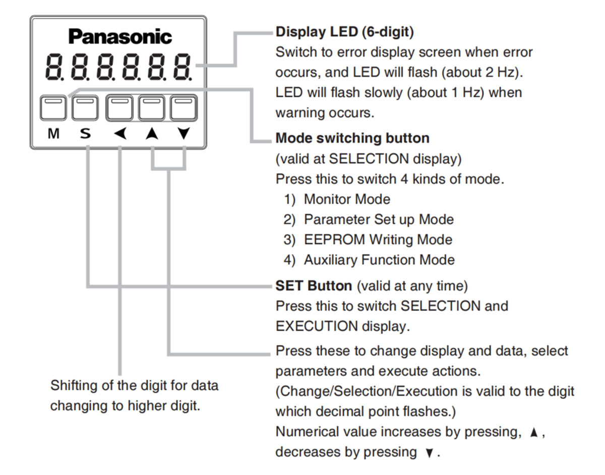
The led front panel of the Panasonic A6 servo motor driver will display the running status of the motor and the alarm code if there's an alarm occurred during the running of the system. It's also the interface of Panasonic A6 servo motor to the operator in parameter setting.
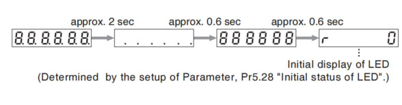
Front panel display shows the following after turning on the power of the driver.
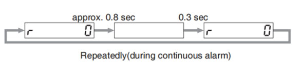
If a driver alarm is generated, the front panel display shows the following repeatedly.
Below shows possible cause of an alarm.
| Alarm No. | Alarm | Content |
|---|---|---|
| A0 | Overload | Load factor is 85% or more the protection level. |
| A1 | Over-regeneration alarm | Regenerative load factor is 85% or more the protection level. |
| A2 | Battery alarm | Battery voltage is 3.2V or lower. |
| A3 | Fan alarm | Fan has stopped for 1 sec. |
| A4 | Encoder communication alarm | The number of successive encoder communication errors exceeds the specified value. |
| A5 | Encoder overheat alarm | The encoder detects overheat alarm. |
| A6 | Oscillation detection alarm | Oscillation or vibration is detected |
| A7 | Lifetime detection alarm | The life expectancy of capacity or fan becomes shorter than the specified time |
| A8 | External scale error alarm | The external scale detects the alarm |
| A9 | External scale communication alarm | The number of successive external scale communication errors exceeds the specified value. |
| AC | Deterioration diagnosis warning | Load characteristic estimates and torque command under constant speed has exceeded set range. |
| C3 | Main power off warning | In case that Pr7.14 (Detection time of main power off warning) is 10 to 1999, the mains power between L1 and L3 has stopped instaneously for more than the time prescribed in Pr7.14. |
Related page → • P.4-6 to 4-85 "Details of Parameter"

SW6712
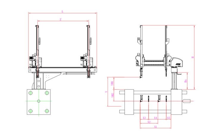
Unit: mm
| X1 | X2 | X3 | X4 | Y | YM1 | YM2 | Z | L | W | H | Payload | 1055 | 607 | 288 | 607 | 1200 | 420 | 780 | 1750 | 2340 | 1700 | 2460 | 8kg |
|---|
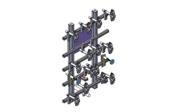
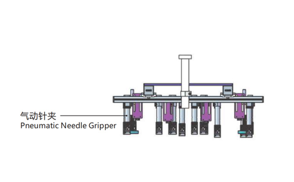
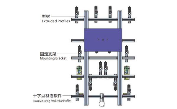
EOAT Assembly Demonstration -- Two Cavities Non-woven Fabric In Mold Insertion
Product Descriptions
Bom List
| Product Name | PN # | Model | Quantity |
|---|---|---|---|
| Extruded Profiles | 4.Y00052 | PEP4040-1000 | 2 |
| Plugs for Profile | 4.Y00072 | PEP4040 | 4 |
| Extruded Profiles | 4.Y000481 | PEP2525-1500 | 2 |
| Extruded Profiles | 4.Y00481 | PEP2525-1000 | 1 |
| Plugs for Profile | 4.Y00070 | PEP2525 | 10 |
| Cross Mounting Bracket for Profiles | 7.Y00356-T | SMBA-2540T | 10 |
| Pneumatic Needle Gripper | 8.Y00025 | GN2010 | 14 |
| Mounting Bracket | 7.Y00308-T | SMBE2-2060T | 14 |
| Mounting Bracket | 7.Y00309-T | SMBE2-3060T | 1 |
What's the Meaning of IML?
IML (In Mould Labeling) is an automation solution of injection molding which is mostly in production of food containers especially the production of containers for dairy products. It's originated from USA and widely used now around the world. An IML system will include the injection molding machine, a mould, an IML robot and other auxiliary machinery. With this system, the robot will put the IML label into the mould to be injected as part of the IML container.
In an IML system, the importance of the injection molding machine, the mold, the IML robot, the label are the key to start a successful IML project. It's possible to start a successful IML project with a suitable injection molding machine, the qualified label, the well designed mold and the right IML robot system. It's very important to have the whole system well tested before delivery.
Since the first IML system put on market in 2009, SWITEK IML had been delivered to clients in more than 43 countries and regions with our largest overseas market in Russian and India. With years' experience of cooperating with the injection molding machine and IML mold makers in China, SWITEK is now the best turn-key IML solutions provider from China to provide you with a price smart turn-key IML Solutions.


