switek email

sales06@switek.biz

switek whatsapp

+86 186 5927 5869

Shopping

Subscrib to Us

.
SWITEK Robotic Arms for Injection Molding Machine Installation Instruction -- Chapter 7: Function Configures

One Stop Robotic Arms for Injection Molding Machine Purchasing

SWITEK Robotic Arms for Injection Molding Machine Installation Instruction -- Chapter 7: Function Configures
Abstract

The programming of a robotic arm for injection molding machine is not only a setting of the axis position, enable/disable the cylinders and other EOAT parts etc., but also include the signal settings to have the robot communicating with the injection molding machine, the product settings, the stack setting, machine sconfigure, system settings, security point settings etc. In this chapter we're discussing how are these parameters of the robotic arms configured step by step.

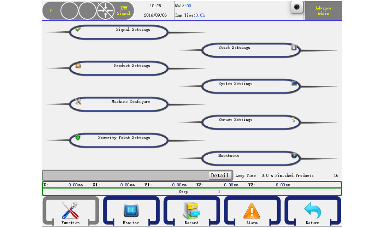
In the stop status and then click the function menu item on the main menu bar to go into function configures page. As shown below:
robot installation

You can select function group in this page, click the item will open the corresponding detail settings page. The structure Settings can only set by the Advance Administrator.

7.1 Signal Settings

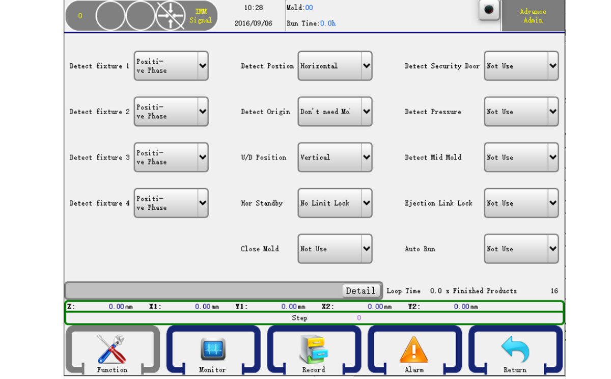
Click the Signal Settings item to go into the signal setting page, as shown below:
robot installation
  • Detect Fixture 1-4:
    Positive: Check if the fixture input signal is on.
    Reverse: Check if the fixture input signal is off.
  • Sub Fixture
    Positive: Check if the fixture input signal is on.
    Reverse: Check if the fixture input signal is off.
  • Detect Position:
    Horizontal:The posture must be horizontal position when executing traverse action.
    Vertical:The posture ust be vertical pose when executing traverse action.
    No Limit: No Limit: Does not detect.
  • Detect Origin:
    Horizontal:The posture of the robot arm must be horizontal position when executing traverse action.
    Vertical:The posture of the robot arm must be vertical pose when executing traverse action.
    No Limit: No Limit: Does not detect.
  • U/D Position:
    Horizontal:The posture of the robot arm must be horizontal position when executing traverse action.
    Vertical:The posture of the robot arm must be vertical pose when executing traverse action.
    No Limit: No Limit: Does not detect.
  • Hor Standby:
    Limit Lock Mold: The mold close enabled only after the robotic arm up moved to the standby position.
    No Limit Lock Mold: The mold close enabled as soon as the robotic arm started to move up.
  • Close Mold:
    Use: The robot will move into the mold for parts picking only after the Mold Opened signal given after the Mold Closed signal, otherwise a Mold not Locked alarm given.
    Not Use:The robot will not detect the Mold Closed signal but will enter the mold for parts picking as soon as the Mold Opened signal received.
  • Detect Security Door:
    Use: Alarm when the security door is open when the robot is auto running, no matter which action.
    Not Use:Alarm when the security door is open when executing the arm down action.
  • Detect Pressure:
    Use: The robot will check the pressure of the compressed air, if lower than the standard value an alarm given.
    No Use: Not check the pressure.
  • Detect Mid Mold:
    Use: The robot will check the mid mold signal, if there is no mid mold signal when the robot arm down inside the mold, an alarm given.
    No Use: Not check the mid mold signal.
  • Ejection Link Lock:
    Use: The ejector enable signal would be off after mold open finished and the "Ejector Enable" signal must be inserted into the program.
    No Use: The Ejector Enable signal will be normally On.
  • Auto Run
    Use: The robot will check the Auto signal from the injection molding machine, if not detected in Auto mode an alarm would be given. No Use: The robot will not check the Auto signal from the injection molding machine.

7.2 Product Settings

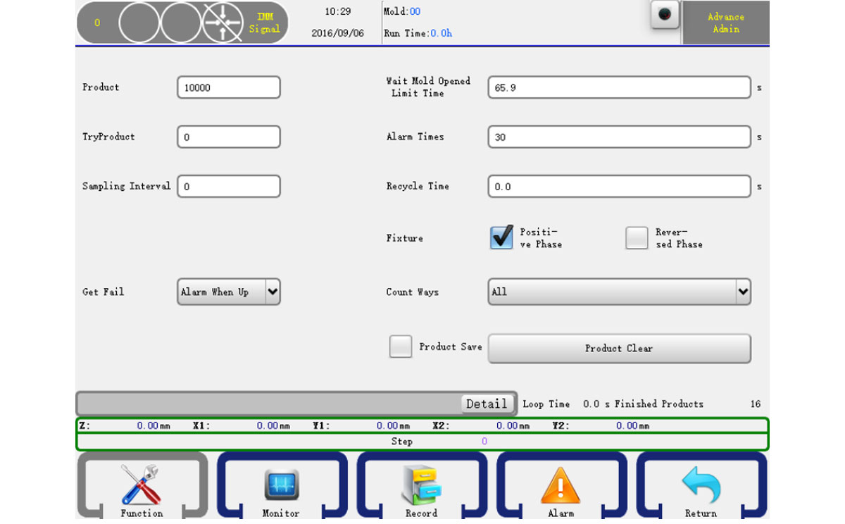
Click the Product Settings button to go into the product setting page, as shown below:
robot installation
  • Product: Setting the product count, when over the number of you set, it alarms.
  • Trial production: The number of products for trial producdtion.
  • Sampling Interval: The interval of which a sample would be taken for quality checking.
  • Get Fail:
    Arm up alarm: Arm up and alarm when checked the failure signal.
    Alarm: Alarm immediated after the failure of parts picking.
  • Wait Mold Opened Limited Time: The time to wait Mold Opened signal, the robot will alarm if the waiting time is longer than the setting.
  • Alarm Times: The time of continued alarming.
  • Product Clear: Clear the finished product count.
  • Recycle Time: When choose the Mold Locked function, it's the time when the system received the signal of Mold Closed to the signal of Mold Enable OFF.
7.3 Machine Configure

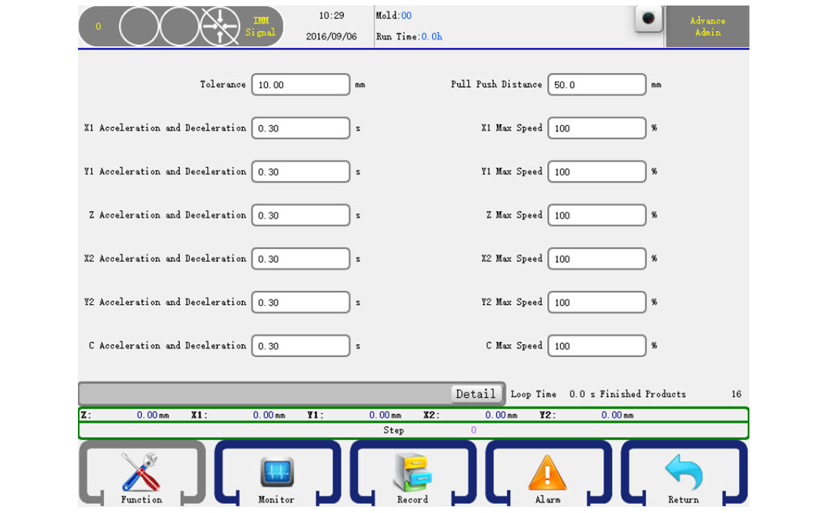
Click the Machine Configure button to go into the machine configure page, as shown below:
robot installation

Tolerance: The tolerance between the sent pulse and feedback pulse of servo.
Safety Zone: A safety zone between arms and sub arms.
X, Y, Z Acceleration and Deceleration: The servo axis acceleration and decelatiion time.
X, Y, Z Max Speed: The max speed of the servo axis.

7.4 Security Point Settings

Click the Security Point Settings button to go into the security point settings page, as shown below:

robot installation
  1. Press the X Menu item on the top to select the axis you want to see.
    Max: The max for axis to move.
    Maximum inside: The maximum position that the axis could move in machine.
    Minimum inside: The minimum position that the axis could move in machine.
    +Test: Test the servo positive pulse.
    -Test: Test the servo reserve pulse.
    Clear: Clear the test data.
    When you have done, just click the set i button to confirm.
  2. Press the Y1 menu item on the top to select the axis you want to see.
    Maximum standby: Set the standby position Y1 axis maximum points.
    Distance back to origin: Y1's position before OPR operation.
    Press the Y1 menu item on the top to select the axis you want to see.
  3. Press the Z menu item on the top to select the axis you want to see.
    Safety zone inside: Setting a number which is safety zone inside of machine.
    Safety zone outside: A safety distance number out of the machine.
  4. Press the C menu item on the top to select the axis you want to see.
    Transverse safe range: A safety angle when move towards transverse.
  5. Press the Structure menu item on the top. As shown below:
    Min increase inside of X axis: Min position for X when arm rise in machine.
    Max increase inside of X axis: Max position for X when arm rise.
    Min increase outside of Y axis: Min position for Y when arm rise out of machine.
    Max increase outside of Y axis: Max position for Y when arm rise.

Attention: You can modify the X's minimum, maximum position in the mechanical parameters page X axis parameter field.

7.5 Stack Settings

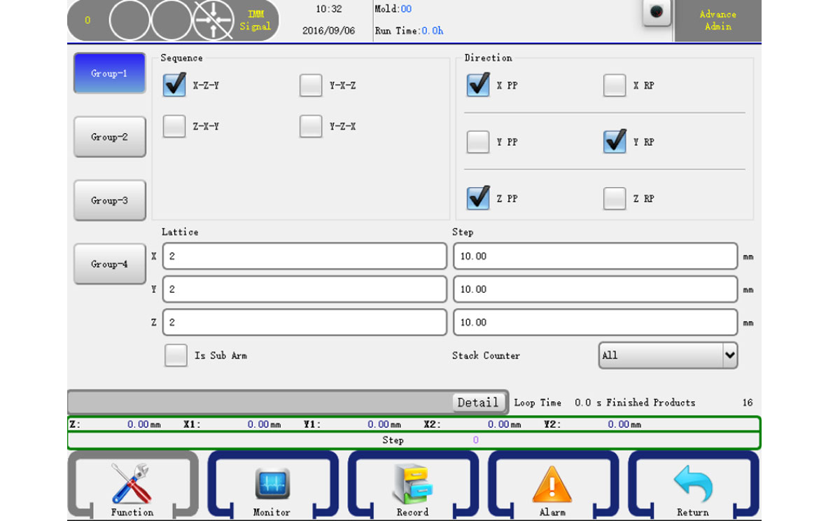
Click the Stack Settings item to go into the stack settings page, as shown below:
robot installation

There are four group stack setting in our system.
Sequence: Select the stack sequence
X RP: If checked, the robot will stack reverse on the X axis.
Y RP: If checked, the robot will stack reverse on the Y axis.
Z RP: If checked, the robot will stack reverse on the Z axis.

7.6 System Settings

7.6.1 Setting

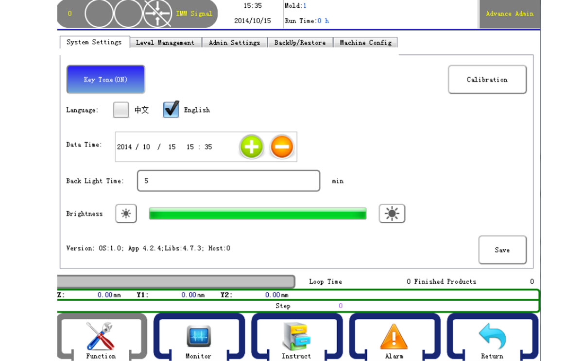
Click the System Settings item to go into the system settings page, as shown below:
robot installation

Key Tone: When press the keyboard will beep if on.
Language: Select the interface language.
Date Time: Set the current date time.
Back Light Time: If no action in the setting time, the back light will turn off.
Version: The version of the system.
Click the Save to confirm after the system settings done.

7.6.2 Level Management

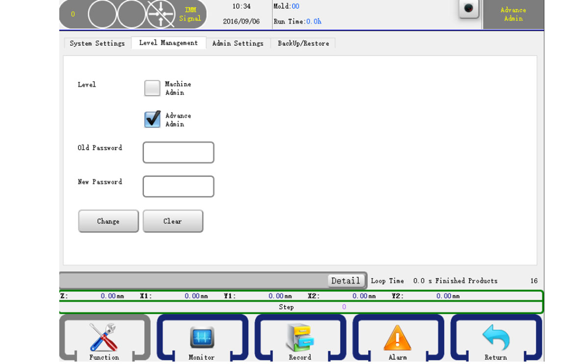
Click the Level Management item to go into the system settings page, as shown below:
robot installation

Level management can change the basic information while administer can modify any parameters. Enter the old password and then input a new one and confirm, you can change the password.

7.6.3 Backup/Restore

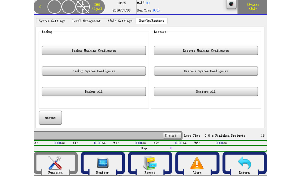
Click the Backup/Restore item to go into the system settings page, as shown below:
robot installation

You can use USB to backup or restore "Machine Parameters", "System Parameters" and "Mold Parameters" or select all to backup/restore.

7.7 Structure Settings

Click the Struct Settings item to go into the structure settings page, as shown below:
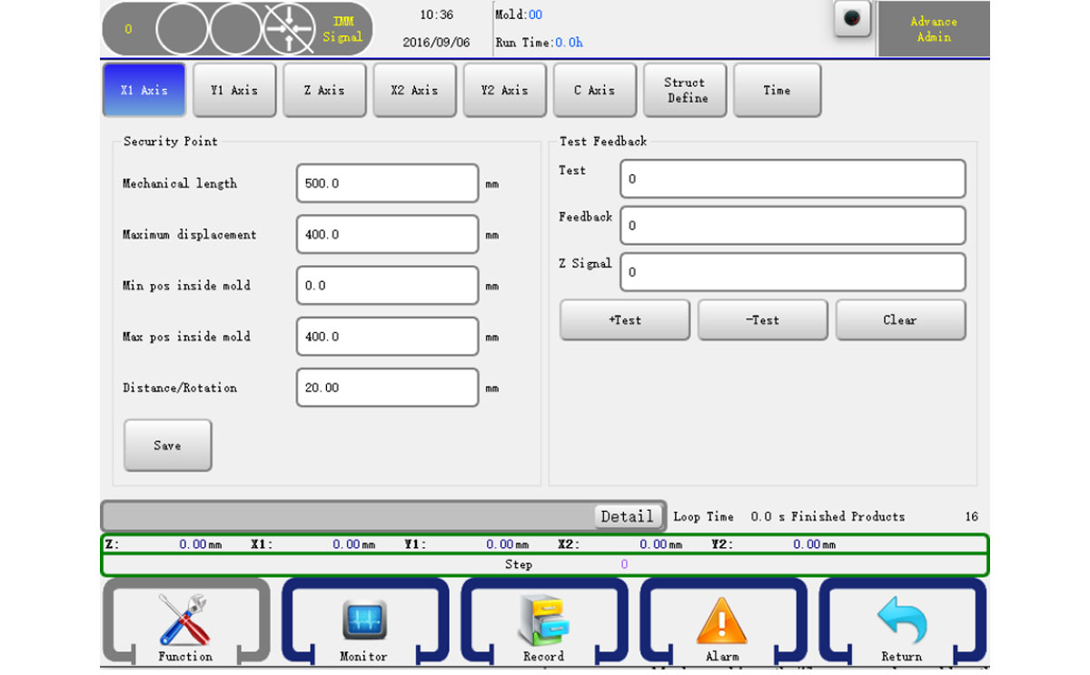
robot installation

Mechanical Length: The axis mechanical length.
Distance/Rotation: The distance of one rotation of the servo.
You can also set other parameters as 5.4 please press the save button to confirm your change. WARNING: Struct define may cause damage to the machine and personal injury! Please contract the manufacturer.

7.8 Maintains

Click the Maintains item to go into the maintain page, as shown below:
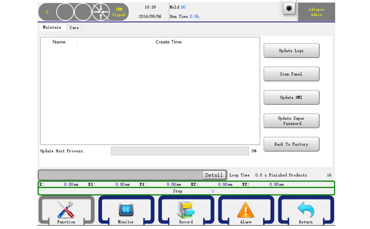
robot installation

You can update the control panel system by a USB. Put the system update packet to a U disk. Click the Refresh button and wait for a while the page will show the system version if it can check the system update packet from the disk. If it can't, just press the refresh button again or use another U disk. If it check the system update packet, just click the Update button to start update system. After finish will show a message and the system will restart and then you can unplugin your U disk.


Best Buy Robotic Arm for Injection Molding Machine
injection robot

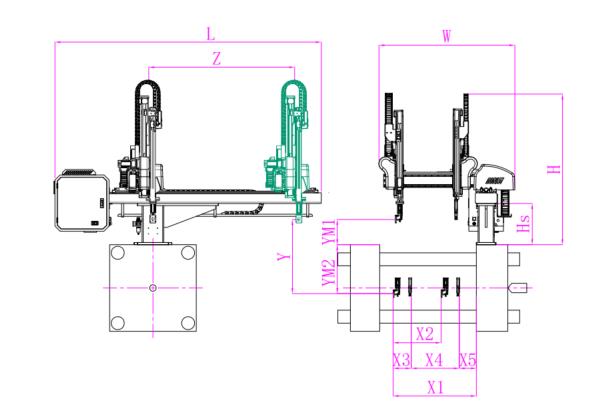
SW7522DS

injection robot

Unit: mm

X1 X2 X3 X4 Y YM1 YM2 Z L W H Payload
1785 1680 0 0 2200 650 1550 3120 4160 2850 2830 15kg

The Application of End of Robotic Arm Tooling

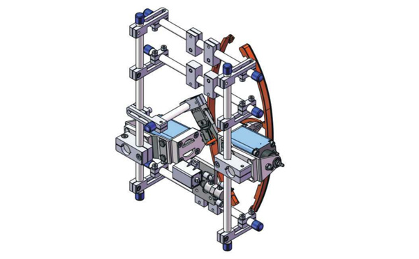
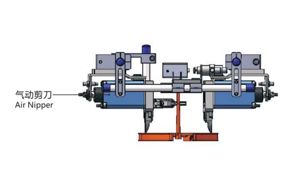
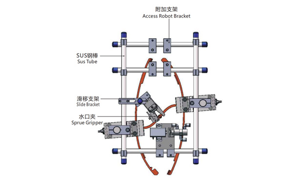
EOAT Assembly Demonstration -- Two Cavities Parts Picking EOAT with Runner Gripping

Two Cavities Parts Picking EOAT with Runner Gripping

Product Descriptions

Bom List

Product Name PN # Model Quantity
Quick Changer 7.Y00175 QCS-G100 1
Sprue Gripper 8.Y00050 GR12-12CP 1
Plugs for Profile 4.Y00069 PEP2518 10
Cross Mounting Bracket for Profiles 7.Y00194 SMBA-2525T 6
Extruded Profile 4.Y00455 PEP2518-1000 2
Vacuum Cups VS2 Series 1.Y03085 VS2-SA11 6
Vacuum Cup Fitting 7.Y00703 VM-02-G18 6
Rotative Suspensions 8.Y00061 VFR1421-G18 6
Mounting Bracket 7.Y00200 SMBE1-1440T 6
Connector 1.Y02510 APF-M5 2
Side Manifold Block 7.Y00157 SMB-06M5 2
L-Type Threaded HOse Fitting 1.Y02722 APL6-01 8
Straight Threaded Hose Fitting 1.Y02725 APC6-01 6

Q & A About Robotic Arms and Injection Automation

What's the Meaning of IML?

IML (In Mould Labeling) is an automation solution of injection molding which is mostly in production of food containers especially the production of containers for dairy products. It's originated from USA and widely used now around the world. An IML system will include the injection molding machine, a mould, an IML robot and other auxiliary machinery. With this system, the robot will put the IML label into the mould to be injected as part of the IML container.

In an IML system, the importance of the injection molding machine, the mold, the IML robot, the label are the key to start a successful IML project. It's possible to start a successful IML project with a suitable injection molding machine, the qualified label, the well designed mold and the right IML robot system. It's very important to have the whole system well tested before delivery.

Since the first IML system put on market in 2009, SWITEK IML had been delivered to clients in more than 43 countries and regions with our largest overseas market in Russian and India. With years' experience of cooperating with the injection molding machine and IML mold makers in China, SWITEK is now the best turn-key IML solutions provider from China to provide you with a price smart turn-key IML Solutions.


Email: sales06@switek.biz

WhatsApp

WeChat