sales06@switek.biz

+86 186 5927 5869

Shopping

Subscrib to Us
sales06@switek.biz
+86 186 5927 5869
Shopping
Subscrib to Us

When you make an order of the robotic arm for your injection molding project, we'll have the robotic arm assembled to be either have the parts dropped from the operator side or non operator side according to your project, but some times you'll have to change the dropping of the parts to the other side of the injection molding machine. In this situation you'll have to reverse the installation of the robotic arm. In this chapter we'll a 3 axis servo injection robot with Panasonic servo motor and driver as an example to demonstrate how to have a reversed installation of the robotic arms.
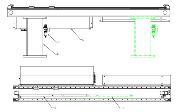
Base Reverse
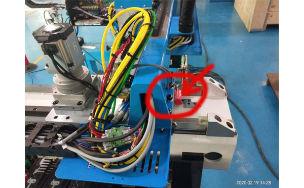
Sensor Reverse 1
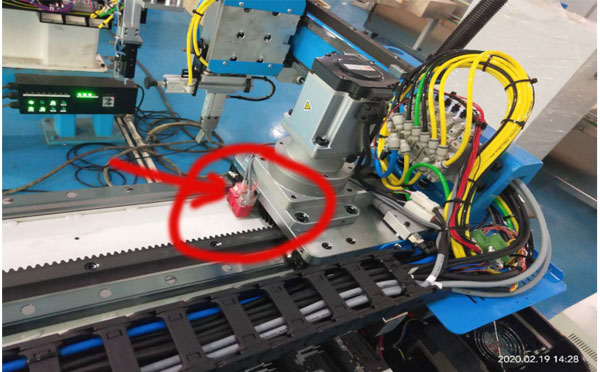
Sensor Reverse 2
Description
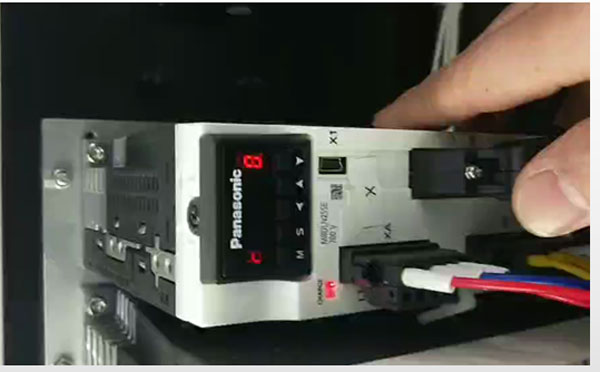
Panasonic A6 Parameter Setting
The Modification Process:
Press key "S" → then press key "M" (One time), find Pr0.00 → press key "S" (One time), if the parameter displayed is "1", modify it to "0"; if its "0" then change it to "1" (press up/down key to modify the parameters). After all the settings finished, press the key "S" for 2 seconds → press key "M" (One time) → press key "S" (One time) → press key "UP" (Keep 7 seconds until the screen display "-----") to save the setting.
Repeat the process above to set the parameters of Pr0.12 and have the robot power off and restart again after all the parameter settings finished. The robot would be origined with the new setting.
WARNING: For the safety of your facility, please conduct any modification of the parameters with the instruction of our online service team. Our service engineer will guide you to finish the whole process step by step.

SW6710
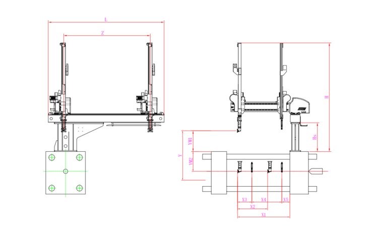
Unit: mm
| X1 | X2 | X3 | X4 | Y | YM1 | YM2 | Z | L | W | H | Payload | 1055 | 607 | 288 | 607 | 1000 | 420 | 580 | 1750 | 2340 | 1700 | 2190 | 8kg |
|---|
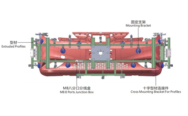
EOAT Assembly Demonstration -- One Cavity Car Bumper Picking EOAT
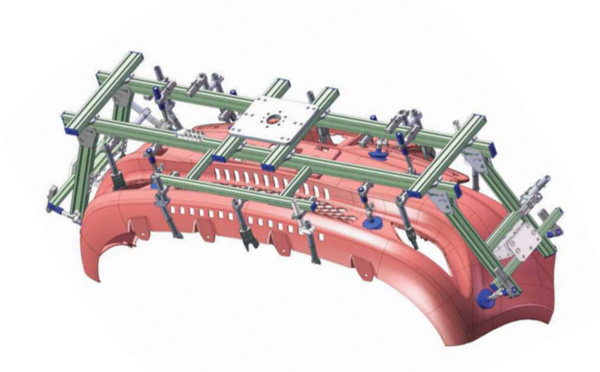
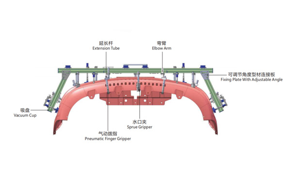
Product Descriptions
What Would be an Economic Solutions for Plastic Faucet Production?
What Would be an Economic Solutions for Plastic Faucet Production?
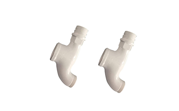
Safe, reliable and easy for production make the PPR faucets getting more and more popular against its counter parts of which made from brass or other metal faucet product. To start a new pleastic faucets production project, what would be an economic configuration?
To produce the plastic faucets economically, you can consider an automation solutions to reduce the man hours, and a two cavities solutions would keep the system economic in investment and easy for maintenance, the machineries for such a system will include:
Fore more information about the faucet and other pipe fittings injection automation solution please feel free to contact Adams from SWITEK to get a turn-key solutions of pipe fittings production.