sales06@switek.biz

+86 186 5927 5869

Shopping

Subscrib to Us
sales06@switek.biz
+86 186 5927 5869
Shopping
Subscrib to Us
Keywords:Panasonic A6 Servo Installation Instruction, Panasonic A6 Driver, Panasonic A6 Series Servo Motor Manual
The setting of the command division and multiplication ratio is the promise of an efficient automation system driven by a Panassonic A6 series of AC servo motor and driver. Here in this chapter we're discussing the relation between Electronic Gear and Position Resolution or Travelling Speed.
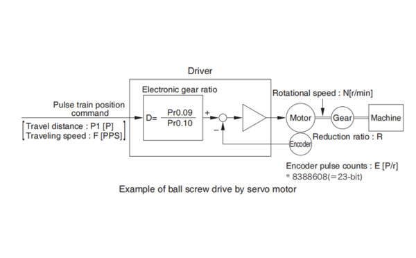
Here we take a ball screw drive as an example of machine.
A travel distance of a ball screw M[mm] corresponding to travel command P1[P], can be described by the following formula (1) by making the lead of ball screw as L[mm]
M=P1 x (D/E) x (1/R) x L ……………(1)
therefore, position resolution (travel distance ΔM per one command pulse) will be described by the formula(2)
ΔM = (D/E) x (1/R) x L ……………(2)
modifying the above formular (2), electronic gear ratio can be found in the formula (3).
D=(ΔM x E x R) x L ……………(3)
Actual travelling velocity of ball screw, V[mm/s] can be described by the formula (4) and the motor rotational speed, N at that time can be described by the formula (5).
V=F x (D/E) x (1/R) x L ……………(4)
N=F x (D/E)/(F x 60) ……………(5)
modifying the above formula (5), electronic gear ratio can be found in the formula (6).
D=(N x E)/(F x 60) ……………(6)
Note →
| 2n | Decimal |
|---|---|
| 20 | 1 |
| 21 | 2 |
| 22 | 4 |
| 23 | 8 |
| 24 | 16 |
| 25 | 32 |
| 26 | 64 |
| 27 | 128 |
| 28 | 256 |
| 29 | 512 |
| 210 | 1024 |
| 211 | 2048 |
| 2n | Decimal |
|---|---|
| 212 | 4096 |
| 213 | 8192 |
| 214 | 16384 |
| 215 | 32768 |
| 216 | 65536 |
| 217 | 131072 |
| 218 | 262144 |
| 219 | 524288 |
| 220 | 1048576 |
| 221 | 2097152 |
| 222 | 4194304 |
| 223 | 8388608 |
| Electronic gear ratio D=ΔM x E x R/L | D=Pr0.09/Pr0.10 | |
|---|---|---|
| Lead of ball screw, L=10mm Gear reduction ratio, R=1 Position resolution, ΔM = 0.005mm Encoder, 23-bit (E=223P/r) | 0.0005 x 223 x 1/10 = 5 x 223/10 x 104 = 41943040/100000 | Pr0.09 = 41943040 Pr0.10 = 100000 |
| Motor rotational speed (r/min), N = F x D/E x 60 | ||
|---|---|---|
| Lead of all screw, L=20 mm Gear reduction ration, R=1 Position resolution, ΔM = 0.0005mm Line driver pulse input, 500 kpps Encoder, 23-bit | 500000 x 0.0005 x 223 x 1/20 x 1/223 x 60 = 750 | |
| Ditto To make it to 2000 r/min | Electronic gear ratio D = N x E/F x 60 | D = Pr0.09/Pr0.10 |
| D = 2000 x 223/500000 x 60 = 2000 x 223/2000 x 500 x 30 = 8388608/15000 | Pr0.09 = 8388608 Pr0.10 = 15000 | |
| Travel distance per command pulse (mm) (Position resolution) ΔM = D/E x 1/R x L | ||
| 2000 x 223/500000 x 60 x 1/223 x 1/1 x 20 = 0.00133 mm | ||
Related page → • P.4-10 "Details of Parameter"

SW6712S
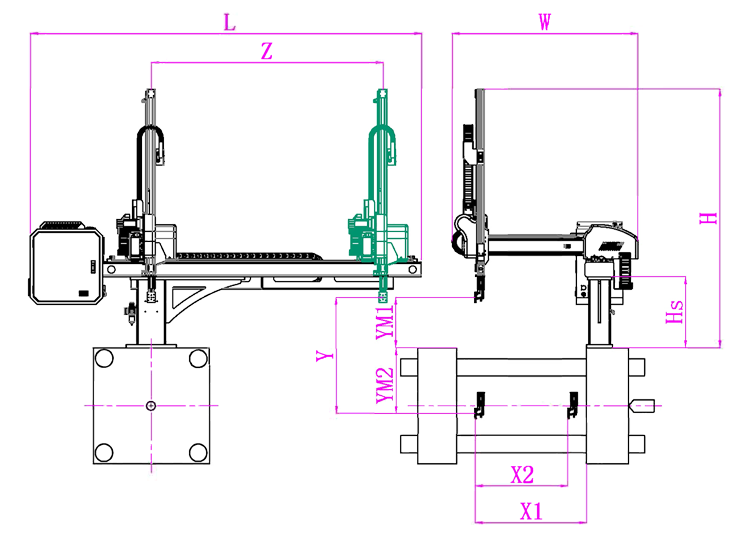
Unit: mm
| X1 | X2 | X3 | X4 | Y | YM1 | YM2 | Z | L | W | H | Payload | 900 | 840 | 0 | 0 | 1200 | 420 | 780 | 2000 | 3020 | 1610 | 2050 | 8kg |
|---|
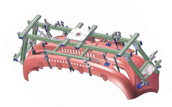
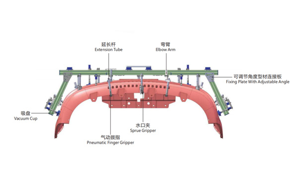
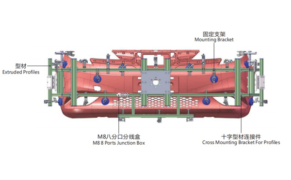
EOAT Assembly Demonstration -- One Cavity Car Bumper Picking EOAT
Product Descriptions
How is SWITEK 4 Cavities Pipe Strap Base Nuts In Mold Insertion System Work?
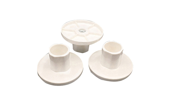
SWITEK 4 cavities pipe strap base nuts in mold insertion system is an automation solutions designed for the production of the PVC pipe strap base which is used for the on ceiling fixing of the pipes, below is the configuration of the pipe strap base production system:
The function of the SWITEK 4 cavities PVC pipe strap base injection automation solution include the nuts sorting, in mold insertion, parts picking and runner cutting. It enables the pipe strap base producer to produce it automatically.
For more solutions of PVC/PPR pipe fittings injection automation solutions please contact Adams from SWITEK to get a professional solutions of turn-key pipe PVC/PPR pipe fittings injection automation solutions.