
sales06@switek.biz

+86 186 5927 5869

Shopping

Subscrib to Us
sales06@switek.biz
+86 186 5927 5869
Shopping
Subscrib to Us

Keywords:Panasonic A6 Servo Installation Instruction, Panasonic A6 Driver, Panasonic A6 Series Servo Motor Manual
You can perform position control based on the positional command (pulse train) from the host controller. This section describes the fundamental setup to be used for the position control.
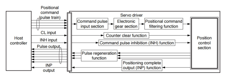
The positional commands of the following 3 types (pulse train) are available.
Set the pulse configuration and pulse counting method based on the specification and configuration of installation of the host controller.
The input terminals can accommodate the following 2 systems.
For line driver output, "Input 2" can also be used without changing the allowable input frequency.
• Relevant parameters
| Parameter | Title | Range | Function |
|---|---|---|---|
| Pr0.05 | Selection of command pulse input | 0 to 2 | You can select either the photocoupler input or the exclusive input for line driver as the command pulse input. 0:Photocoupler input (PULS1, PULS2, SIGN1, SIGN2) 1:Exclusive input for the driver (PULSH1, PULSH2, SIGNH1, SIGNH2) 2:Photocoupler input (PULS1, PULS2, SIGN1, SIGN2) [250 kpulse/s or less] |
| Pr0.06 | Command pulse rotational direction setup | 0 to 1 | Sets the counting direction when command pulse is input. |
| Pr0.07 | Command pulse input mode setup | 0 to 3 | Sets the counting method when command pulse is input. |
This function multiplies the input pulse command from the host controller by the pre-determined driving or multiplying factor and applies the result to the position control section as the positional command. By using this function, desired motor rotations or movement distance per unit input command pulse can be set; or the command pulse frequency can be increased if the desired motor speed cannot be obtained due to limited pulse output capacity of the host controller.
• Relevant parameters
| Parameter No. | Title | Range | Function |
|---|---|---|---|
| Pr0.08 | Command pulse counts per one motor revolution | 0 to 8388608 | Set the command pulses that causes signle turn of the motor shaft. |
| Pr0.09 | 1st numerator of electronic gear | 0 to 1073741824 | Set the numerator of division/multiplication operation made according to the command pulse input. |
| Pr0.10 | Denominator of electronic gear | 1 to 1073741824 | Set the denominator of division/multiplication operation made according to the command pulse input. |
| Parameter No. | Title | Range | Function |
|---|---|---|---|
| Pr0.08 | Command pulse counts per one motor revolution | 0 to 8388608 | Set the command pulses taht causes single turn of the motor shaft. |
| Pr0.09 | 1st numerator of electronic gear | 1 to 1073741824 | Set the Denominator of division/multiplication operation made according to the command pulse input. |
| Pr0.10 | Denominator of electronic gear | 1 to 1073741824 | Set the denominator of division/multiplication operation made according to the command pulse input. |
To make the positional command divided or multiplied by the electronic gear smooth, set the command filter.
• Relevant parameters
| Parameter No. | Title | Range | Unit | Function |
|---|---|---|---|---|
| Pr2.22 | Positional command smoothing filter | 0 to 10000 | 0.1ms | Set up the time constant of the 1st delay filter in response to the positional command. |
| Pr2.23 | Positional command FIR filter | 0 to 10000 | 0.1ms | Set up the time constant of the 1st delay filter in response to the positional command. |
The information on the amount of movement can be sent to the host controller in the form A- and B-phase pulses from the servo driver. When the output source is the encoder, Z-phase signal is output once per motor revolution; or if the feedback scale, the signal is output at absoute zero position. The output resolution, B-phase logic and output source (encoder or external scale) can be set with parameters.
• Relevant parameters
| Parameter No. | Title | Range | Unit | Function |
|---|---|---|---|---|
| Pr0.11 | Output pulse counts per one motor revolution | 1 to 2097152 | P/r | You can set up the output pulse counts per one motor revolution for each OA and OB with the Pr0.11 setup. |
| Pr0.12 | Reversal of pulse output logic | 0 to 3 | — | You can set up the B-phase logic and the output source of the pulse output. With this parameter, you can reverse the phase relation between the A-phase pulse and the B-phase pulse by reversing the B-phase logic. |
| Pr5.03 | Denominator of pulse output division | 0 to 8388608 | — | For application where the number of pulse per revolution is not an integer, this parameter can be set to a value other than 0, and the dividing rating ratio can be set by setting numerator of division to Pr0.11 and denominator of division to Pr5.03. |
| Pr5.33 | >Pulse regenerative output imit setup | 0 to 1 | — | Enable/disable detection of Err28.0 Pulse regenerative limit protection. |
| Pr6.20 | Z-phase setup of external scale | 0 to 400 | μs | Set up the Z phase regenerative width of feedback scale in unit of time |
| Pr6.21 | Serial absolute external scale Z phase setup | 0 to 268435456 | pulse | Full-closed control using serial absolute feedback scale. When outputting pulses by using the feedback scale as the source of the output, set the Z phase output interval in units of A phase output pulses of the feedbackk scales (before multiplied by 4). |
| Pr6.22 | A, B phase external scale pulse output method selection | 0 to 1 | — | Select the pulse regeneration method of A, B and Z parallel feedback scale. |
The deviation counter clear input (CL) clears the counts of positional deviation counter at the position control to 0.
• Relevant parameters
| Parameter No. | Title | Range | Function |
|---|---|---|---|
| Pr5.17 | Counter clear input mode | 0 to 4 | You can set up the clearing conditions of the counter clear input signal. |
The completion of positioning can be verified by the positioning complete output (INP). When the absolute value of the positional deviation counter at the position control is equal to or below the positioning complete range by the parameter, the output is ON. Presence and absence of positional command can be specified as one of judgment conditions.
• Relevant parameters
| Parameter No. | Title | Range | Unit | Function |
|---|---|---|---|---|
| Pr4.31 | Position complete (In-position) range | 0 to 2097152 | Command unit | Set up the timing of positional deviation at which the positioning complete signal (INP1) is output. |
| Pr4.32 | Positioning complete (In-position) output setup | 0 to 10 | — | Select the condition to output the positioning complete signal (INP1). |
| Pr4.33 | INP hold time | 0 to 30000 | 1 ms | Set up the hold time when Pr4.32 Positioning complete output setup = 3. |
| Pr4.42 | 2nd Positioning complete (In-position) range | 0 to 2097152 | Command unit | Set up the timing of positional deviation at which the positioning complete signal (INP2) is output. |
The command pulse input counting process can be forcibly terminated by using the command pulse inhibit input signal (INH). When INH input is ON, the servo driver ignorses the command pulse, disabling pulse counting function. At then, A large number of pulses of the positional command filter function and the command frequency mulitiplication function is cleared.
The default setting of this inhibition function is disable. To use INH function, change the setting of Pr5.18 "Invalidation of command pulse prohibition input".
• Relevant parameters
| Parameter No. | Title | Range | Function |
|---|---|---|---|
| Pr5.18 | Invalidation of command pulse inhibit input | 0 to 1 | Select command pulse inhibit input enable/disable. |
| Pr5.19 | Command pulse inhibit input reading setup | 0 to 5 | Select command pulse inhibit input enable/disable signal reading period. When the status of several signals read during the predetermined reading period are same, update the signal status. |

SW6308S-20
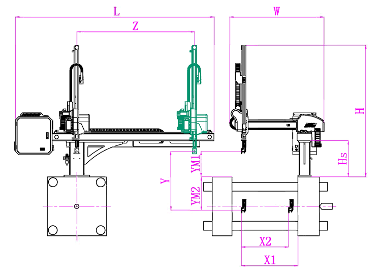
Unit: mm
| X1 | X2 | X3 | X4 | Y | YM1 | YM2 | Z | L | W | H | Payload | 980 | 820 | 0 | 0 | 800 | 235 | 565 | 1280 | 2320 | 1500 | 1690 | 3kg |
|---|
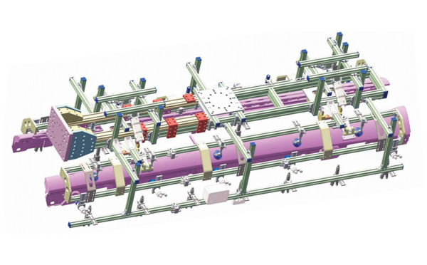
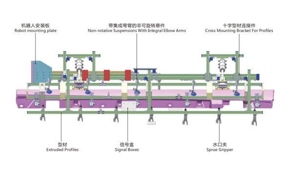
EOAT Assembly Demonstration -- One Cavity Car Threshold Strip Picking EOAT
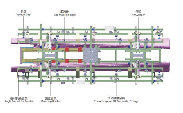
Product Descriptions
Why is SWITEK your best OEM/ODM partner of IML robot?
With more robots manufacturers joint the competition of IML solutions, you'll be able to find many new brands of IML robot from China each year in the Plastic manchinery related exhibitions in your Countries. With so many IML solutions available, how to choose the one best suitable to your project and who would be your reliable partner to provide you with an OEM/ODM service?
As an project oriented injection automation system, IML robot is a custom made system according to the mold design, which made it a team work of R&D, purchasing and after service. And an experienced service team of IML system would be the key to a successful IML project.
With the first IML system on show Chinaplas 2010, SWITEK is now one of the largest IML solutions provider in China with an annual output of more than 200 sets of IML system delivered, we have a complete IML solutions of both top & side entry for IML containers/lids from 100ml to 33L paint buckets. We can not only provide an IML system according to your requirement but also custom make the colors of the IML robot.
For more information of IML robot OEM/ODM service, please feel free to contact Adams from SWITEK to get a reday to work IML system.


