
sales06@switek.biz

+86 186 5927 5869

Shopping

Subscrib to Us
sales06@switek.biz
+86 186 5927 5869
Shopping
Subscrib to Us
Keywords:Panasonic A6 Servo Installation Instruction, Panasonic A6 Driver, Panasonic A6 Series Servo Motor Manual
The correct setup of the parameter and mode of the Panasonic A6 series of servo will ensure the proper working of the Panasonic A6 series of motor and the stability of your machineries and automation system.
This driver is equipped with various parameters to set up its characteristics and functions. This section describes the function and purpose of each parameter. Read and comprehand very well so that you can adjust this driver in optimum condition for your running requirements.
• You can refer and set up the parameter with either one of the following.
1) front panel of the driver
2) combination of the setup support software, "PANATERM" and PC.
Note → How to control the front panel, refer to P.2-74.
It is possible to connect your personal computer to connector X1 of MINAS A6 using a USB cable for personal computer connection. Downloading the setup support software "PANATERM" from out web site and installing it on your personal computer will allow you to perform the following easily. • With the PANATERM, you can execute the followings.
Note → Because no production software such as CD-ROM is available, download the setup support software from our web site and install it on your personal computer.
• USB cable
On the driver, use commercially available USB mini-B connector.
The connector on the personal computer side should be in accordance with the specifications of the PC.
When the cable does not have noise filter, attach a signal line noise filter (DV0P1460) to both ends of the cable.
Related page → • P.4-2 "Details of Parameter" • P.7-26 "Setup support software [PANATERM]"
| Parameter No. | Class name | Group | page | |
|---|---|---|---|---|
| Class | No.* | |||
| 0 | 00 to 18 | Basic setting | Parameter for Basic setting | P.2-52 |
| 1 | 00 to 78 | Gain adjustment | Parameter for Gain adjustment | P.2-52 |
| 2 | 00 to 37 | Damping control | Parameter fro Damping | P.2-55 |
| 3 | 00 to 29 | Verocity/Torque/Full-closed control | Parameter for Verocity/Torque/Fullclosed control | P.2-57 |
| 4 | 00 to 57 | I/F monitor setting | Parameter for I/F monitor setting | P.2-58 |
| 5 | 00 to 86 | Enhancing setting | Parameter for Enhancing setting | P.2-60 |
| 6 | 00 to 98 | Special setting | Parameter for Special setting | P.2-63 |
| 7 | 00 to 93 | Special setting | Parameter for Special setting | P.2-66 |
| 8 | 00 to 19 | For manufacturer's use | Not be used. | P.2-67 |
| 9 | 00 to 50 | For manufacturer's use | Not be used. | P.2-68 |
| 15 | 00 to 35 | For manufacturer's use | Not be use | P.2-69 |
*The Parameter No. consists of 2 digits.
| Symbol | Control mode | Setup value of Pr0.01 |
|---|---|---|
| P | Position control | 0 |
| S | Velocity control | 1 |
| T | Torque control | 2 |
| F | Full-closed control | 6 |
| P/S | Position (1st/Velocity (2nd) control | 3* |
| P/T | Position (1st/Torque (2nd) control | 4* |
| S/T | Velocity (1st/Torque (2nd) control | 5* |
* When you select the combination mode of 3, 4 or 5, you can select either 1st or 2nd with control mode switching input (C-MODE).
When C-MODE is ON: 1st mode selection
When C-MODE is OFF: 2nd mode selection
Do not enter the command 10ms before/after the switching.
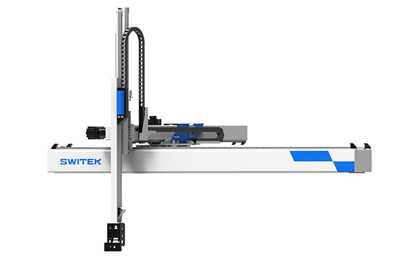
SW7730DS
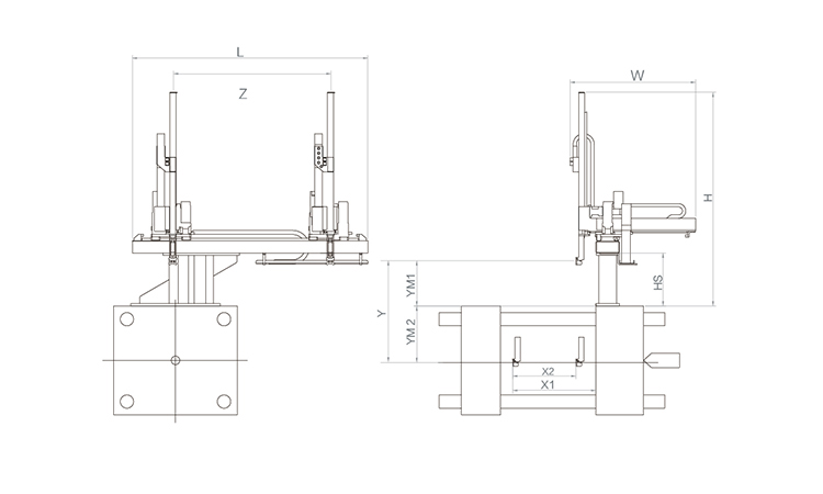
Unit: mm
| X1 | X2 | X3 | X4 | Y | YM1 | YM2 | Z | L | W | H | Payload | 2250 | 1720 | 0 | 0 | 3000 | 780 | 2220 | 4000 | 5050 | 3005 | 3440 | 75kg |
|---|
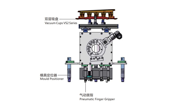
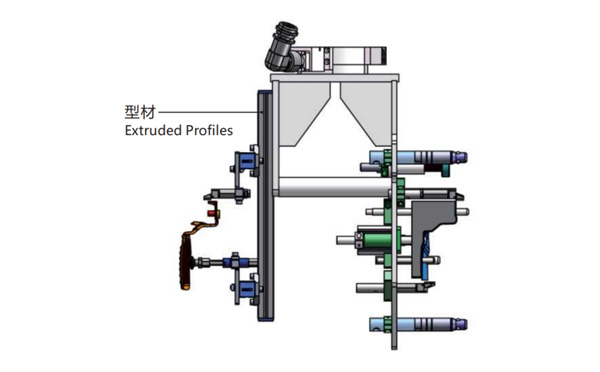
EOAT Assembly Demonstration -- One Cavity In Mold Insertion EOAT With Mold Positioner
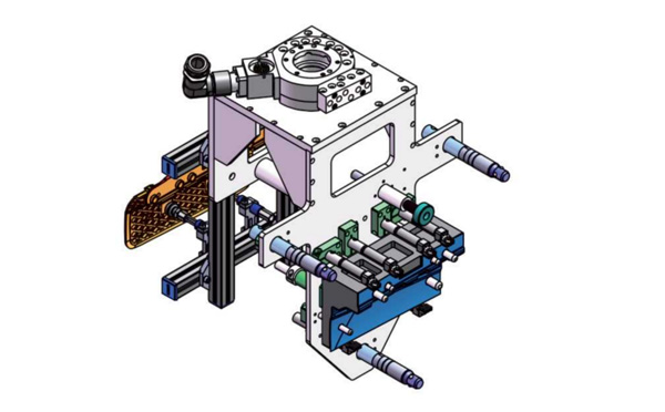
Product Descriptions
Bom List
| Product Name | PN # | Model | Quantity |
|---|---|---|---|
| Extruded Profiles | 4.Y00481 | PEP2525-1500 | 1 |
| Plugs for Profile | 4.Y00070 | PEP2525 | 8 |
| Mould Positioner | 8.Y00088 | GMP20A | 3 |
| Vacuum Cups VS2 Series | 1.Y05310 | VS2-SA20 | 2 |
| Rotative Suspensions | 8.Y00061 | VFR1421-G18 | 2 |
| Pneumatic Finger Gripper | 8.Y00084 | GFR14-95G | 7 |
| Extension Tube | 7.Y00733 | SMBY14-50 | 6 |
| Mounting Bracket | 7.Y00200-T | SMBE1-1440T | 3 |
| Cross Mounting Bracket for Profiles | 7.Y00194-T | SMBA-2525T | 4 |
| Vacuum Cup Fittings | 7.Y00703 | VM02-G18 | 2 |
Will Hybrid An Ideal Injection Molding Machine for IML Project?
Hybrid injection molding machine, a combination of the all electric injection molding machine and the hydraulic injection molding machine, it's no doubt one of the best injection molding machine for your IML project. A hybrid injection molding machine will have the precision of plastic injection also the much lower cost against the all electric injection molding machine.
One of the best buy hybrid injection molding machine made in China is the LDY series of hybrid injection molding machine made by Haida, one of the injection molding machine manufacturer founded in 1992 and is famous for the reliability of the injection molding machines. The LDY series of hybrid injection molding machine is their key products for thin-wall container production markets with a clamping force ranging from 100~420T.
For your IML project, the best IML robot to match Haida LDY series hybrid injection molding machine would be SWITEK SW8 Series IML robot, with control systems by European system provider SigmaTek, the cycle time of SW8 series of IML robot can reach 2.0s for the IML production of small size thin-wall containers or lids. It's one of the fastest IML robot made in China.


