sales06@switek.biz

+86 186 5927 5869

Shopping

Subscrib to Us
sales06@switek.biz
+86 186 5927 5869
Shopping
Subscrib to Us
Keywords:Panasonic A6 Servo Installation Instruction, Panasonic A6 Driver, Panasonic A6 Series Servo Motor Manual
Control output signal of desired function can be assigned to I/F connector. Logic of the output pin cannot be changed.
| Applicable parameter | Default parameter setting (): decimal notation | Default Setup | ||||||
|---|---|---|---|---|---|---|---|---|
| Position/Full-closed control | Verocity control | Torque control | ||||||
| Signal | Signal | Signal | ||||||
| Pin No. | 10 11 | Title of signal | SO1 output | Pr4.10 | 00030303h(197379) | BRK-OFF | BRK-OFF | BRK-OFF |
| Symbol | Pin No.10:SO1- Pin No.11:SO1+ | |||||||
| Pin No. | 34 35 | Title of signal | SO2 output | Pr4.11 | 00020202h(131586) | S-RDY | S-RDY | S-RDY |
| Symbol | Pin No.34:SO2- Pin No.35:SO2+ | |||||||
| Pin No. | 36 37 | Title of signal | SO3 output | Pr4.12 | 00010101h(65793) | ALM | ALM | ALM |
| Symbol | Pin No.36:SO3- Pin No.37:SO3+ | |||||||
| Pin No. | 38 39 | Title of signal | SO4 output | Pr4.13 | 00050504h(328964) | INP | AT-SPEED | AT-SPEED |
| Symbol | Pin No.38:SO4- Pin No.39:SO4+ | |||||||
| Pin No. | 12 | Title signal | SO5 output | Pr4.14 | 00070707h(460551) | ZSP | ZSP | ZSP |
| Symbol | SO5 | |||||||
| Pin No. | 40 | Title of signal | SO6 output | Pr4.15 | 00060606h(394758) | TLC | TLC | TLC |
| Symbol | SO6 | |||||||
Note → • The function is changed by the setting of parameter. For details, refer to P.4-39. See "Functions assignable to control output" as shown below. [—]: No function assigned. P.3-56 | ||||||||
| Title of signal | Servo-Alarm output | Related control mode | P | S | T | F | ||
| Symbol | ALM | Default assignment | 36,37 (SO3) | I/F circuit | P.3-35 | |||
| ||||||||
| Title of signal | Servo-Ready output | Related control mode | P | S | T | F | ||
| Symbol | S-RDY | Default assignment | 34,35 (SO2) | I/F circuit | P.3-35 | |||
| ||||||||
| Title of signal | External brake release signal | Related control mode | P | S | T | F | ||
| Symbol | BRK-OFF | Default assignment | 10,11 (SO1) | I/F circuit | P.3-35 | |||
| ||||||||
| Title of signal | Positioning complete | Related control mode | P | S | T | F | ||
| Symbol | INP | Default assignment | 38,39 (SO4) | I/F circuit | P.3-35 | |||
| Title of signal | Positioning complete 2 | Related control mode | P | S | T | F | ||
| Symbol | INP2 | Default assignment | — | I/F circuit | P.3-35 | |||
| ||||||||
| Title of signal | Speed arrival output | Related control mode | P | S | T | F | ||
| Symbol | AT-SPEED | Default assignment | 38,39 (SO4) | I/F circuit | P.3-35 | |||
| ||||||||
| Title of signal | Torque in-limit signal output | Related control mode | P | S | T | F | ||
| Symbol | TLC | Default assignment | 40 (SO6) | I/F circuit | P.3-35 | |||
| ||||||||
| Title of signal | Zero-speed detection output signal | Related control mode | P | S | T | F | ||
| Symbol | ZSP | Default assignment | 12 (SO5) | I/F circuit | p.3-35 | |||
| ||||||||
| Title of signal | Speed coincidence output | Related control mode | P | S | T | F | ||
| Symbol | V-COIN | Default assignment | — | I/F circuit | P.3-35 | |||
| ||||||||
| Title of signal | Alarm output 1 | Related control mode | P | S | T | F | ||
| Symbol | WARN1 | Default assignment | — | I/F circuit | P.3-35 | |||
| ||||||||
| Title of signal | Alarm output 2 | Related control mode | P | S | T | F | ||
| Symbol | WARN2 | Default assignment | — | I/F circuit | p.3-35 | |||
| ||||||||
| Alarm No. | Alarm | Content | Pr6.27*1 | Pr4.40/Pr4.41*2 | Pr6.38 Corresponding bit *3 |
|---|---|---|---|---|---|
| A0 | Overload protection | Load factor is 85% or more the protection level. | ○ | 1 | bit7 |
| A1 | Over-regeneration alarm | Regenerative load factor is 85% or more the protection level. | ○ | 2 | bit5 |
| A2 | Battery alarm | Battery voltage is 3.2V or lower. | Fixed at no time limit. | 3 | bit0 |
| A3 | Fan alarm | Fan has stopped for 1 sec.*4 | ○ | 4 | bit6 |
| A4 | Encoder communication alarm | The number of successive encoder communication errors exceeds the specified value. | ○ | 5 | bit4 |
| A5 | Encoder overheat alarm | The encoder detects overheat alarm. | ○ | 6 | bit3 |
| A6 | Oscillation detection alarm | Oscillation or vibration is detected. | ○ | 7 | bit9 |
| A7 | Lifetime detection alarm | The life expectancy of capacity or fan becomes shorter than the specified time. | Fixed at no time limit. | 8 | bit2 |
| A8 | External scale error alarm | The feedback scale detects the alarm. | ○ | 9 | bit8 |
| A9 | External scale communication alarm | The number of successive feedback scale communication errors exceeds the specified value. | ○ | 10 | bit10 |
| AC | Deterioration diagnosis warning *5 | Load characteristic estimates and torque command under constant speed has exceeded the set range. | ○ | 22 | bit7 |
| C3 | Main power off warning | In case that Pr7.14 (Detection time of main power off warning) is 10 to 1999, the mains power between L1 and L3 has stopped instantaneously for more than the time prescribed in Pr7.14. | ○ | 14 | bit14 |
*1 The "○" means that a time in the range 1s to 10s or no time can be selected through Pr6.27 "Warning latching time". Note that the battery warning and the end of life warning have no time limit.
*2 Select the warning output signal 1 (WARN1) or warning output signal 2 (WARN2) through Pr4.40 "Warning output select 1" or Pr4.41 "Warning output select 2". When the set value is 0, all warnings are ORed before being output. Do not set to any value other than those specified in the table above.
*3 A warning detection can be masked by Pr6.38 "Warning mask setup" Corresponding bits are shown in the table. Warning is masked with bit = 1.
*4 The upper fan on the H-frame driver stops during servo OFF to save energy. This is normal and no fan alarm is displayed.
*5 Invalidated when Pr6.97 "Function expansion setting 3" bit1 = 0.
| Pin No. | — | Title of signal | Deterioration diagnosis velocity output | Related control mode | P | S | T | F |
| Symbol | V-DIAG | I/F circuit | P.3-36 | |||||
| ||||||||
| Pin No. | — | Title of signal | Position compare output | Related control mode | P | S | T | F |
| Symbol | CMP-OUT | I/F circuit | P.3-36 | |||||
| •The output transistor is turned ON when the actual position has passed the position set by the parameter. Setting for all control modes is required when using the position compare output, (CMP-OUT). In case setting is made only to one or two control modes, Err33.4 "Output function number error 1 protection" or Err33.5 "Output function number error 2 protection" will occur. | ||||||||
| Pin No. | 42 | Title of signal | Analog monitor output 2 | Related control mode | P | S | T | F |
| Symbol | IM | I/F circuit | P.3-36 | |||||
| ||||||||
| Pin No. | 43 | Analog monitor output 1 | Related control mode | P | S | T | F | |
| Symbol | SP | I/F circuit | P.3-36 | |||||
| ||||||||
| Pin No. | 13, 15 17, 25 | Title of signal | Signal ground | Related control mode | P | S | T | F |
| Symbol | GND | I/F circuit | — | |||||
| ||||||||
| Pin No. | 50 | Title of signal | Frame ground | Related control mode | P | S | T | F |
| Symbol | FG | I/F circuit | — | |||||
| ||||||||

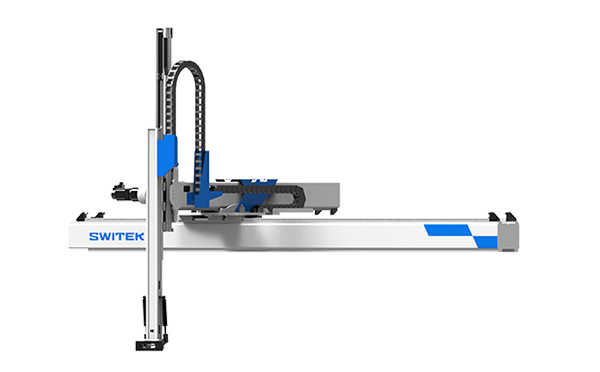
SW6710S
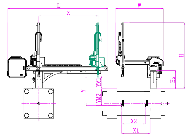
Unit: mm
| X1 | X2 | X3 | X4 | Y | YM1 | YM2 | Z | L | W | H | Payload | 900 | 750 | 0 | 0 | 1000 | 420 | 580 | 1750 | 2780 | 1610 | 1930 | 8kg |
|---|
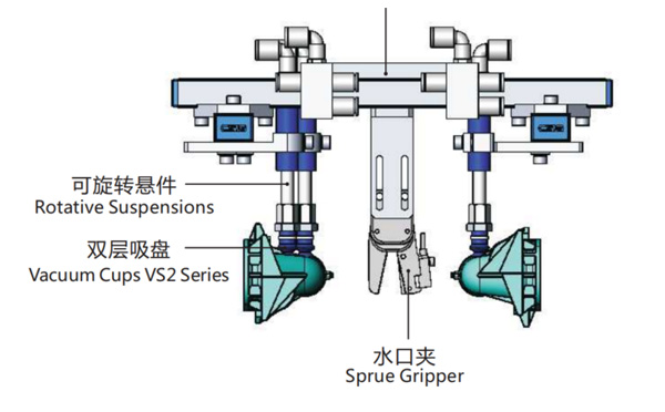
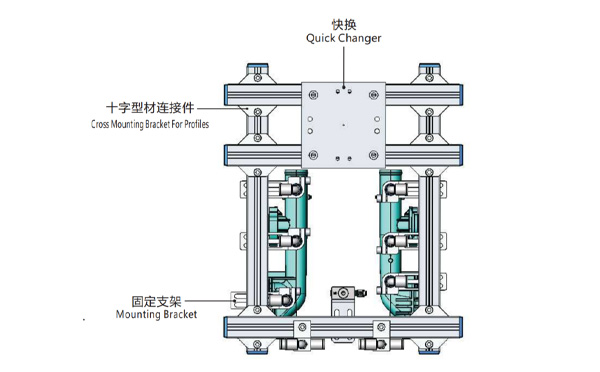
EOAT Assembly Demonstration -- Two Cavities Parts Picking EOAT with Runner Gripping
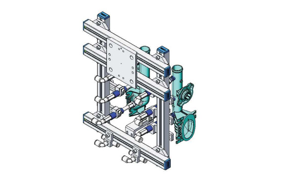
Product Descriptions
Bom List
| Product Name | PN # | Model | Quantity |
|---|---|---|---|
| Quick Changer | 7.Y00175 | QCS-G100 | 1 |
| Sprue Gripper | 8.Y00050 | GR12-12CP | 1 |
| Plugs for Profile | 4.Y00069 | PEP2518 | 10 |
| Cross Mounting Bracket for Profiles | 7.Y00194 | SMBA-2525T | 6 |
| Extruded Profile | 4.Y00455 | PEP2518-1000 | 2 |
| Vacuum Cups VS2 Series | 1.Y03085 | VS2-SA11 | 6 |
| Vacuum Cup Fitting | 7.Y00703 | VM-02-G18 | 6 |
| Rotative Suspensions | 8.Y00061 | VFR1421-G18 | 6 |
| Mounting Bracket | 7.Y00200 | SMBE1-1440T | 6 |
| Connector | 1.Y02510 | APF-M5 | 2 |
| Side Manifold Block | 7.Y00157 | SMB-06M5 | 2 |
| L-Type Threaded HOse Fitting | 1.Y02722 | APL6-01 | 8 |
| Straight Threaded Hose Fitting | 1.Y02725 | APC6-01 | 6 |
What Would be the Best Picking Robot for LK FA1200 in a Dustbin Production Project?
FA1200 is a Two-palten energy-saving servo injection molding machine produced by LK machinery for the production of automotive parts, home appliances, sanitation buckets, pallets, pipe fittings etc. As a Two-platen injection molding machine, it's an ideal choice for the production of deep cavity container like dustbin. For a project of dustbin production, which robot would be the best for this injection molding machine?
As a Two-platen injection molding machine with a clamping force of 12000kN, LK FORZA FA1200 has an opening stroke of 2100mm with a max mold thickness up to 1300mm, it'll be suitable to produce a dustbin with a maximum height up to 650mm without IML. To pick the dustbin only the 3 axis servo injection robot SW7518DS by SWITEK Automation would be the best one.
SW7518DS is a medium sized 3 axis servo injection robot designed for the injection molding machine with clamping force from 500T ~ 1500T with a payload up to 15kg. As a kick-back designed robot, it'll provide 30% more space for EOAT moving and a perfect mate to a deep cavity product like dustbin picking.
Starting from 2006, SWITEK is providing the OEM/ODM service of robotic arms for injection automation from Sprue picker to heavy duty robot with payload up to 75kg to match injection molding machine up to 4000T with turn-key injection automation solutions. For more information about SWITEK robotic arms and injection automation solution please contact Adams, your personal consultant of injecdtion automation solution integration.