
sales06@switek.biz

+86 186 5927 5869

Shopping

Subscrib to Us
sales06@switek.biz
+86 186 5927 5869
Shopping
Subscrib to Us
Keywords:Panasonic A6 Servo Installation Instruction, Panasonic A6 Driver, Panasonic A6 Series Servo Motor Manual
In the applications where the motor drives the vertical axis, this brake would be used to hold and prevent the work (moving load) from falling by gravity while the power to the servo is shut off.
The following shows the example when the brake is controlled by using the brake release output signal (BRK-OFF) of the driver.
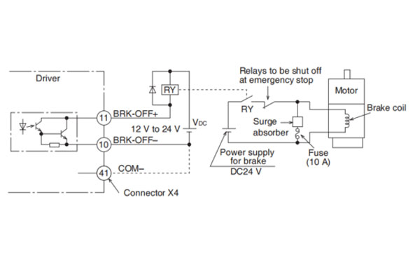
Note → 1. The Brake coil has no polarity.
Caution → 2. Power supply for the brake to be provided by customer. Do not co-use the power supply for the brake and for the control signals (VDC).
3. Install a surge absorber as the above Fig. shows to suppress surge voltage generated by ON/OFF action of the relay (RY). When you use a diode, note that the time from the brake release to brake engagement is slower than that of the case of using a surge absorber.
4. For a surge absorber, refer to P.7-146, "Recommended Components" of supplement.
5. Recommended components are specified to measure the brake releasing time.
Reactance of the cable varies depending on the cable length, and it might generate surge voltage.
Select a surge absorber so that relay coil voltage (max. rating:30V, 50mA) and terminal voltage may not exceed the rating.
Note →
| Motor series | Motor output | Static friction torque N*m | Rotor inertia x 10-4kg*m2 | Engaging time ms | Releasing time ms | Exciting current DC A (at cool-off) | Releasing voltage | Permissible work (J) per one braking | Permissible total work x 103J | Permissible angular acceleration rad/s2 |
|---|---|---|---|---|---|---|---|---|---|---|
| MSMF | 50 W, 100W | 0.294 or more | 0.002 | 35 or less | 20 or less | 0.30 | DC1V or more | 39.2 | 4.9 | 30000 |
| 200 W, 400 W | 1.27 or more | 0.018 | 15 or less | 50 or less | 0.36 | 137 | 44.1 | |||
| 750 W | 2.45 or more | 0.075 | 70 or less | 20 or less | 0.42 | 196 | 147 | |||
| 1.0 kW (☐80) | 3.80 or more | 185 | 80.0 | |||||||
| 1.0kW(☐100), 1.5kW, 2.0kW | 8.0 or more | 0.175 | 50 or less | 15 or less | 0.81 | DC2 V or more | 600 | 50 | 10000 | |
| 3.0 kW | 12.0 or more | 80 or less | 900 | |||||||
| 4.0 kW | 16.2 or more | 1.12 | 110 or less | 50 or less | 0.90 | 1470 | 2160 | |||
| 5.0 kW | 22.0 or more | 1545 | 2000 | |||||||
| MQMF | 100 W | 0.39 or more | 0.018 | 15 or less | 20 or less | 0.30 | DC1 V or more | 105 | 44.1 | 3000 |
| 200 W, 400 W | 1.6 or more | 0.075 | 70 or less | 0.36 | 185 | 80.0 | ||||
| MDMF | 1.0kW, 1.5kW, 2.0kW | 13.7 or more | 1.12 | 100 or less | 50 or less | 0.79 | DC2 V or more | 1470 | 2160 | 10000 |
| 3.0 kW | 22.0 or more | 110 or less | 0.90 | 1545 | 2000 | |||||
| 4.0 kW | 25.0 or more | 4.7 | 80 or less | 25 or less | 1.29 | 1800 | 3000 | 5440 | ||
| 5.0 kW | 44.1 or more | 4.1 | 150 or less | 30 or less | 3100 | 5108 | ||||
| MGMF | 850 W, 1.3kW, 1.8 kW | 13.7 or more | 1.12 | 100 or less | 50 or less | 0.79 | DC2 V or more | 1470 | 2160 | 10000 |
| 2.4kW | 25.0 or more | 4.7 | 80 or less | 25 or less | 1.29 | 1800 | 3000 | 5440 | ||
| 2.9 kW | ||||||||||
| 4.4 kW | 44.1 or more | 3.93 | 150 or less | 30 or less | 3100 | 5108 | ||||
| MHMF | 50 W, 100 W | 0.38 or more | 0.002 | 35 or less | 20 or less | 0.30 | DC1 V or more | 39.2 | 4.9 | 30000 |
| 200 W, 400 W | 1.6 or more | 0.018 | 50 or less | 0.36 | 105 | 44.1 | ||||
| 750 W, 1.0kW (☐80) | 3.8 or more | 0.075 | 70 or less | 0.42 | 185 | 80.0 | ||||
| 1.0kW(☐130), 1.5kW | 13.7 or more | 1.12 | 100 or less | 50 or less | 0.79 | DC2 V or more | 1470 | 2160 | 10000 | |
| 2.0 kW, 3.0kW, 4.0kW | 25 or more | 4.7 | 80 or less | 25 or less | 1.29 | 1800 | 3000 | 5440 | ||
| 5.0 kW | 44.1 or more | 4.1 | 150 or less | 30 or less | 3100 | 5108 |
SW7518DS
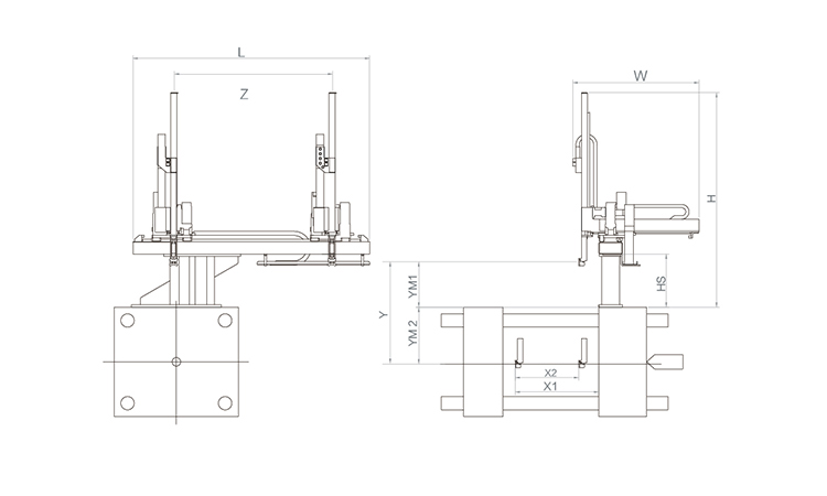
Unit: mm
| X1 | X2 | X3 | X4 | Y | YM1 | YM2 | Z | L | W | H | Payload | 1785 | 1320 | 0 | 0 | 1800 | 500 | 1300 | 3120 | 4160 | 2480 | 2650 | 15kg |
|---|
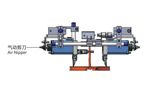
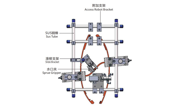
EOAT Assembly Demonstration -- Two Cavities Parts Picking EOAT with Runner Cutting by Air Nipper
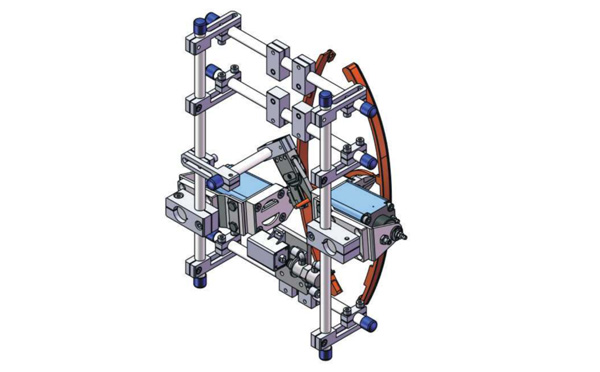
Product Descriptions
Bom List
| Product Name | PN # | Model | Quantity |
|---|---|---|---|
| Sus Tube | 4.Y00021 | PST12-1500 | 2 |
| Air Nipper | 1.Y00004 | GT-NY25 | 2 |
| Straight Blades for Plastic | 1.Y00037 | NY25AJ | 2 |
| Fixing Block | 7.Y00633 | SCE2-25 | 2 |
| Tube Plugs | 1.Y03638 | PST12-1500 | 11 |
| Cross Connector | 7.Y00027 | SMBT-2012 | 2 |
| Access Robot Bracket | 7.Y00002 | SMBH1-12M6 | 6 |
| L-Type Thread Hose Fitting | 1.Y02809 | APL6-M5 | 3 |
| Slide Bracket | 7.Y00004 | SCF4-1240W16 | 7 |
| Slide Bracket | 7.Y00001 | SMBS-12T16 | 7 |
| Sprue Gripper | 8.Y00091 | GR12-12-CN | 1 |
| Cross Connector | 7.Y00020 | SMBT-1212 | 1 |
For 20/33L Pails IML Prodcution, Which Injection Molding Machine Would Be the Best One for This IML Project?
For the IML production of 20/33L pails, HaiDa machinery, which was founded in 1992, has a special high precision injection molding machine HD700U specialized for the IML production of 20/33L IML pails. With a clamping force of 700T and enlarged opening stroke up to 1060mm, which enable it to IML produce a deeper pails.
As a mate to Haida HD700U, the largest IML Robot among the SW8 Series of SWITEK Automation SW850 provide a perfect side entry IML solutions for the IML production of 20/33L pails. The combination of Haida HD700U + SWITEK SW850 IML Robot will provide the IML pails producer a price smart pails IML Solutions.


