sales06@switek.biz

+86 186 5927 5869

Shopping

Subscrib to Us
sales06@switek.biz
+86 186 5927 5869
Shopping
Subscrib to Us
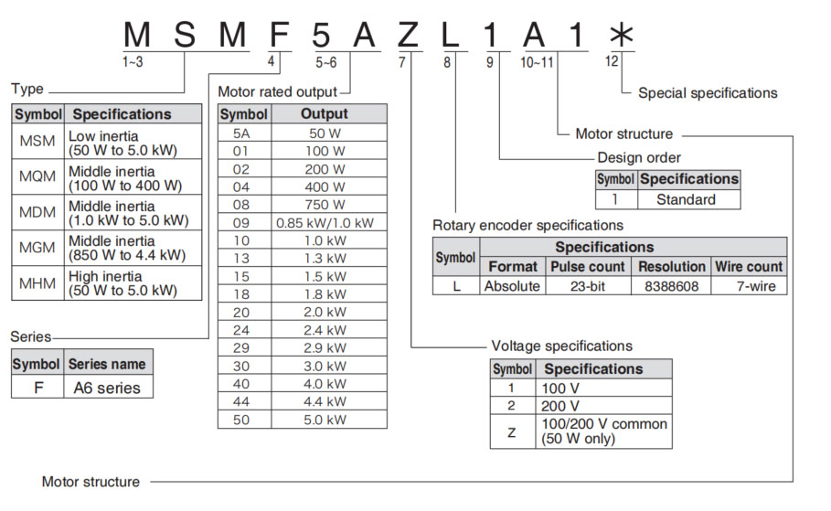
Keywords:Panasonic A6 Servo Motor, Panasonic A6 Servo Motor Driver, Panasonic A6 Servo Motor setting instruction
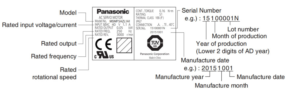
The name plate of the servo motor and driver provide an overall guideline of the motor and driver, here in this chapter we're explaining in detail the meaning of the datas on the name plate of the Panasonic A6 series of AC servo and motor.
MSMF (Below ☐80)
| Symbol | Shaft | Holding brake | Oil seal | Motor I/F | |||||
|---|---|---|---|---|---|---|---|---|---|
| 10 dig | 11 dig | Round | Key way Threaded | Without | With | Without | With | Connector type | Leadwire type |
| A | 1 | • | • | • | • | ||||
| A | 2 | • | • | • | • | ||||
| B | 1 | • | • | • | • | ||||
| B | 2 | • | • | • | • | ||||
| C | 1 | • | • | • | • | ||||
| C | 2 | • | • | • | • | ||||
| D | 1 | • | • | • | • | ||||
| D | 2 | • | • | • | • | ||||
| S | 1 | • | • | • | • | ||||
| S | 2 | • | • | • | • | ||||
| T | 1 | • | • | • | • | ||||
| T | 2 | • | • | • | • | ||||
| U | 1 | • | • | • | • | ||||
| U | 2 | • | • | • | • | ||||
| V | 1 | • | • | • | • | ||||
| V | 2 | • | • | • | • | ||||
Note → • For details of specific model, refer to the Dimensions of Supplement.
Related page → • P.1-19 "Check of the Combination of the Driver and Motor" • P.7-84 to 7-107 "Dimensions of motor"
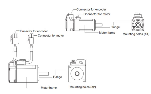
Motor structure
MQMF, MHMF (Below ☐80)
| Symbol | Shaft | Holding brake | Oil Seal | Motor I/F | ||||||
|---|---|---|---|---|---|---|---|---|---|---|
| 10 dig | 11 dig | Round | Key way Threaded | Without | With | Without | With | With (Protective lip) | Connector type | Leadwire type |
| A | 1 | • | • | • | • | |||||
| A | 2 | • | • | • | • | |||||
| B | 1 | • | • | • | • | |||||
| B | 2 | • | • | • | • | |||||
| C | 1 | • | • | • | • | |||||
| C | 2 | • | • | • | • | |||||
| C | 3 | • | • | • | • | • | ||||
| C | 4 | • | • | • | • | • | ||||
| D | 1 | • | • | • | • | |||||
| D | 2 | • | • | • | • | |||||
| D | 3 | • | • | • | ||||||
| D | 4 | • | • | • | ||||||
| S | 1 | • | • | • | • | |||||
| S | 2 | • | • | • | • | |||||
| T | 1 | • | • | • | • | |||||
| T | 2 | • | • | • | • | |||||
| U | 1 | • | • | • | • | |||||
| U | 2 | • | • | • | • | |||||
| U | 3 | • | • | • | • | |||||
| U | 4 | • | • | • | • | |||||
| V | 1 | • | • | • | • | |||||
| V | 2 | • | • | • | • | |||||
| V | 3 | • | • | • | • | |||||
| V | 4 | • | • | • | • | |||||
MSMF, MDMF, MGMF, MHMF (Above ☐80)
| Symbol | Shaft | Holding brake | Oil seal | Motor I/F | |||||
|---|---|---|---|---|---|---|---|---|---|
| 10 dig | 11 dig | Round | Key way Threaded | Without | With | With | With (Protective lip) | Connector JN2 | Connector JL10 |
| C | 5 | • | • | • | • | ||||
| C | 6 | • | • | • | • | ||||
| C | 7 | • | • | • | • | ||||
| C | 8 | • | • | • | • | ||||
| D | 5 | • | • | • | • | ||||
| D | 6 | • | • | • | • | ||||
| D | 7 | • | • | • | • | ||||
| D | 8 | • | • | • | • | ||||
| G | 5 | • | • | • | • | ||||
| G | 7 | • | • | • | • | ||||
| G | 8 | • | • | • | • | ||||
| H | 5 | • | • | • | • | ||||
| H | 6 | • | • | • | • | ||||
| H | 7 | • | • | • | • | ||||
| H | 8 | • | • | • | • | ||||
Note → • For details of specific model, refer to the Dimensions of Supplement.
Related page → • F.1-19 "Check of the Combination of the Driver and the Motor" • P.7-84 to 7-107 "Dimensions of motor"
•MSMF 50 W to 1.0kW (☐80)
•MHMF 50 W to 1.0kW (☐80)
•MQMF 100 W to 400W
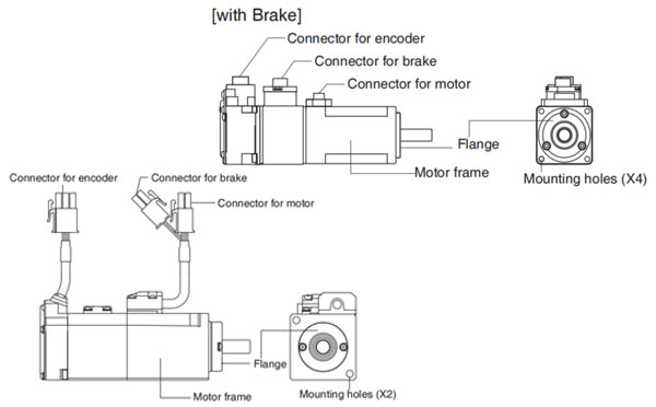
e.g.): Low inertia type (MSMF series, 50W), High inertia type (MHMF series, 50W)
•MSMF 1.0 kW (☐100) to 5.0kW
•MDMF 1.0 kW to 5.0kW
•MGMF 850 W to 4.4kW
•MHMF 1.0 kW (☐130) to 5.0 kW
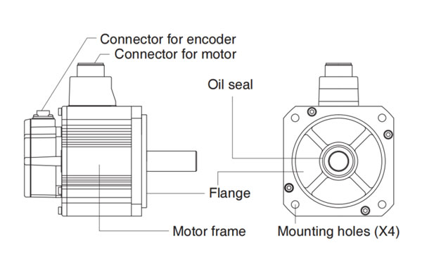
e.g.): Middle inertia type (MDMF series, 1.0 kW)
Note → For details of specific model, refer to the Dimensions of Supplement. (P.7-84 to 7-107)
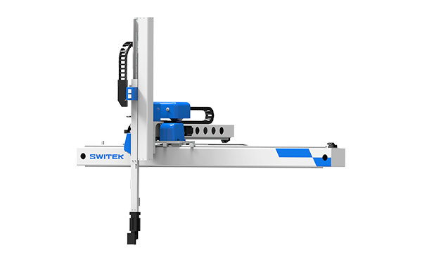
SW7112DS
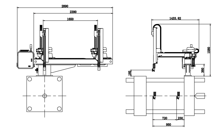
Unit: mm
| X1 | X2 | X3 | X4 | Y | YM1 | YM2 | Z | L | W | H | Payload | 950 | 720 | 0 | 0 | 1200 | 425 | 775 | 1650 | 2710 | 1434 | 1780 | 5kg |
|---|
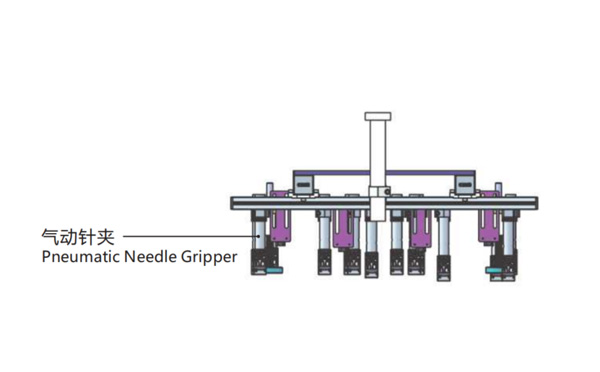
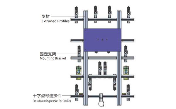
EOAT Assembly Demonstration -- Two Cavities Non-woven Fabric In Mold Insertion
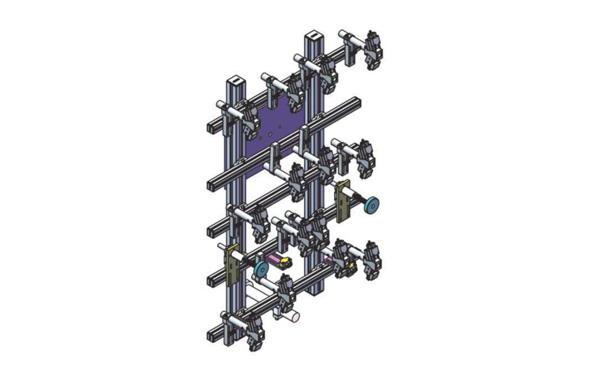
Product Descriptions
Bom List
| Product Name | PN # | Model | Quantity |
|---|---|---|---|
| Extruded Profiles | 4.Y00052 | PEP4040-1000 | 2 |
| Plugs for Profile | 4.Y00072 | PEP4040 | 4 |
| Extruded Profiles | 4.Y000481 | PEP2525-1500 | 2 |
| Extruded Profiles | 4.Y00481 | PEP2525-1000 | 1 |
| Plugs for Profile | 4.Y00070 | PEP2525 | 10 |
| Cross Mounting Bracket for Profiles | 7.Y00356-T | SMBA-2540T | 10 |
| Pneumatic Needle Gripper | 8.Y00025 | GN2010 | 14 |
| Mounting Bracket | 7.Y00308-T | SMBE2-2060T | 14 |
| Mounting Bracket | 7.Y00309-T | SMBE2-3060T | 1 |
What's the Standard Function of a SWITEK Petri Dish Auto-packing System?
SWITEK Petri Dish Packing System is an automation system for the production of the disposible PS Petri dishes from parts picking to assembly to bag packing automatically. It's a system of which will help the small and medium sized Petri dish producer to produce a "Tamination Free" Padish with proper packing automatically. It'll help the Petri dish producers to guarantee the quality of the Petri dishes and reduce the production cost will all the production process done automatically.
For a standard SWITEK Petri dish packing system with a top entry picking robot, the function of the system will include the picking of the Petri dish, the assembly and stacking of the assembled Petri dish, the film packing and sealing of the Petri dish. Beside these standard function, SWITEK will also offer the optional functions below:
Anyway, to reduce the system purchase cost and fasten the start up of the Petri dish packing system, the best option is to buy a turn-key solution of Petri dish packing so SWITEK will have the packing system tested with the mold before delivery to ensure that the system is ready to work.
For more information about SWITEK Petri dish packing solutions, contact Adams from SWITEK immediately, for a just in time advisory of your Petri dish project.