sales06@switek.biz

+86 186 5927 5869

Shopping

Subscrib to Us
sales06@switek.biz
+86 186 5927 5869
Shopping
Subscrib to Us
Keywords:Panasonic A6 Servo Installation Instruction, Panasonic A6 Driver, Panasonic A6 Series Servo Motor Manual
The correct setup of the parameter and mode of the Panasonic A6 series of servo will ensure the proper working of the Panasonic A6 series of motor and the stability of your machineries and automation system.
| Parameter No. | Title | Range | Default | Unit | Turning on of power supply | Related Control Mode | Detail page | ||||||
|---|---|---|---|---|---|---|---|---|---|---|---|---|---|
| Class | No. | A, B-frame | C-frame | D,E,F-frame | P | S | T | F | |||||
| 4 | 00 | Sl1 input selection (Pin No.8) | 0 to OOFFFFFFh | 8553090 | — | ○ | ○ | ○ | ○ | ○ | 4-39 | ||
| 4 | 01 | Sl2 input selection (Pin No.9) | 0 to 00FFFFFFh | 8487297 | — | ○ | ○ | ○ | ○ | ○ | 4-40 | ||
| 4 | 02 | Sl3 input selection (Pin no.26) | 0 to 00FFFFFFh | 9539850 | — | ○ | ○ | ○ | ○ | ○ | |||
| 4 | 03 | Sl4 input selection (Pin No.27) | 0 to 00FFFFFFh | 394758 | — | ○ | ○ | ○ | ○ | ○ | |||
| 4 | 04 | Sl5 input selection (Pin No.28) | 0 to 00FFFFFFh | 4108 | — | ○ | ○ | ○ | ○ | ○ | |||
| 4 | 05 | Sl6 input selection (Pin No.29) | 0 to 00FFFFFFh | 197379 | — | ○ | ○ | ○ | ○ | ○ | |||
| 4 | 06 | Sl7 input selection (Pin No.30) | 0 to 00FFFFFFh | 3847 | — | ○ | ○ | ○ | ○ | ○ | |||
| 4 | 07 | Sl8 input selection (Pin No.31) | 0 to 00FFFFFFh | 263172 | — | ○ | ○ | ○ | ○ | ○ | |||
| 4 | 08 | Sl9 input selection (Pin No.32) | 0 to 00FFFFFFh | 328965 | — | ○ | ○ | ○ | ○ | ○ | |||
| 4 | 09 | Sl10 input selection (Pin No.33) | 0 to 00FFFFFFh | 3720 | — | ○ | ○ | ○ | ○ | ○ | |||
| 4 | 10 | SO1 output selection (Pin No.10, 11) | 0 to 00FFFFFFh | 197379 | — | ○ | ○ | ○ | ○ | ○ | 4-41 | ||
| 4 | 11 | SO2 output selection (Pin No.34, 35) | 0 to 00FFFFFFh | 131586 | — | ○ | ○ | ○ | ○ | ○ | |||
| 4 | 12 | SO3 output selection (Pin No.36, 37) | 0 to 00FFFFFFh | 328964 | — | ○ | ○ | ○ | ○ | ○ | |||
| 4 | 13 | SO4 output selection (Pin No.38, 39) | 0 to 00FFFFFFh | 328964 | — | ○ | ○ | ○ | ○ | ○ | |||
| 4 | 14 | SO5 output selection (Pin No.12) | 0 to 00FFFFFFh | 460551 | — | ○ | ○ | ○ | ○ | ○ | |||
| 4 | 15 | SO6 output selection (Pin No. 40) | 0 to 00FFFFFFh | 394758 | — | ○ | ○ | ○ | ○ | ○ | |||
| 4 | 16 | Type of analog monitor 1 | 0 to 28 | 0 | — | ○ | ○ | ○ | ○ | 4-42 | |||
| 4 | 17 | Analog monitor 1 output gain | 0 to 214748364 | 0 | — | ○ | ○ | ○ | ○ | ||||
| 4 | 18 | Type of analog monitor 2 | 0 to 28 | 4 | — | ○ | ○ | ○ | ○ | ||||
| 4 | 19 | Analog monitor 2 output gain | 0 to 214748364 | 0 | — | ○ | ○ | ○ | ○ | ||||
| 4 | 20 | For manufacturer's use | — | 0 | — | ||||||||
| 4 | 21 | Analog monitor output setup | 0 to 2 | 0 | — | ○ | ○ | ○ | ○ | 4-44 | |||
| 4 | 22 | Analog input 1 (AI1) offset setup | -5578 to 5578 | 0 | 0.366 mV | ○ | ○ | ○ | ○ | ||||
| 4 | 23 | Analog input 1 (AI1) filter | 0 to 6400 | 0 | 0.01 ms* | ○ | ○ | ○ | ○ | ||||
| 4 | 24 | Analog input (AI1) overvoltage setup | 0 to 100 | 0 | 0.1 V* | ○ | ○ | ○ | ○ | ||||
| 4 | 25 | Analog input 2 (AI2) offset setup | -342 to 342 | 0 | 5.86 mV | ○ | ○ | ○ | ○ | ||||
| 4 | 26 | Analog input 2 (AI2) filter | 0 to 6400 | 0 | 0.01 ms* | ○ | ○ | ○ | ○ | ||||
| 4 | 27 | Analog input 2(AI2) overvoltage setup | 0 to 100 | 0 | 0.1V* | ○ | ○ | ○ | ○ | ||||
| 4 | 28 | Analog input 3 (AI3) offset setup | -342 to 342 | 0 | 5.86 mV | ○ | ○ | ○ | ○ | ||||
| 4 | 29 | Analog input 3(AI3) filter | 0 to 6400 | 0 | 0.01 ms* | ○ | ○ | ○ | ○ | 4-45 | |||
| 4 | 30 | Analog input 3(AI3) overvoltage setup | 0 to 100 | 0 | 0.1 V* | ○ | ○ | ○ | ○ | ||||
| 4 | 31 | Positioning complete (In-position) range | 0 to 2097152 | 10 | Command unit | ○ | ○ | ||||||
| 4 | 32 | Positioning complete (In-position) output setup | 0 to 10 | 0 | — | ○ | ○ | ||||||
| 4 | 33 | INP hold time | 0 to 30000 | 0 | 1 ms | ○ | ○ | 4-46 | |||||
| 4 | 34 | Zero-speed | 10 to 20000 | 50 | r/min | ○ | ○ | ○ | ○ | ||||
| 4 | 35 | Speed coincidence range | 10 to 20000 | 50 | r/min | ○ | ○ | ||||||
| 4 | 36 | At-speed (Speed arrival) | 10 to 20000 | 1000 | r/min | ○ | ○ | 4-47 | |||||
| 4 | 37 | Mechanical brake action at stalling setup | 0 to 10000 | 0 | 1 ms | ○ | ○ | ○ | ○ | ||||
| 4 | 38 | Mechanical brake action running setup | 0 to 10000 | 0 | 1 ms | ○ | ○ | ○ | ○ | ||||
| 4 | 39 | Brake release speed setup | 30 to 3000 | 30 | r/min | ○ | ○ | ○ | ○ | ○ | 4-48 | ||
| 4 | 40 | Selection of alarm output 1 | 0 to 28 | 0 | — | ○ | ○ | ○ | ○ | ||||
| 4 | 41 | Selection of alarm outpu 1 | 0 to 28 | 0 | — | ○ | ○ | ○ | ○ | ||||
| 4 | 42 | 2nd Position complete (In-position) range | 0 to 2097152 | 10 | Command unit | ○ | ○ | ||||||
| 4 | 44 | Position compare output pulse width setting | 0 to 32767 | 0 | 0.1 ms | ○ | ○ | ○ | 4-49 | ||||
| 4 | 45 | Position compare output polarity select | 0 to 63 | 0 | — | ○ | ○ | ○ | |||||
| 4 | 47 | Pulse output select | 0 to 7 | 0 | — | ○ | ○ | ○ | ○ | ○ | |||
| 4 | 48 | Position compare value 1 | -2147483648 to 2147483647 | 0 | Command unit | ○ | ○ | ||||||
| 4 | 49 | Position compare value 2 | -2147483648 to 2147483647 | 0 | Command unit | ○ | ○ | 4-50 | |||||
| 4 | 50 | Position compare value 3 | -2147483648 to 2147483647 | 0 | Command unit | ○ | ○ | ||||||
| 4 | 51 | Position compare value 4 | -2147483648 to 2147483647 | 0 | Command unit | ○ | ○ | ||||||
| 4 | 52 | Position compare value 5 | -2147483648 to 2147483647 | 0 | Command unit | ○ | ○ | ||||||
| 4 | 53 | Position compare value 6 | -2147483648 to 2147483647 | 0 | Command unit | ○ | ○ | ||||||
| 4 | 54 | Position compare value 8 | -2147483648 to 2147483647 | 0 | Command unit | ○ | ○ | ||||||
| 4 | 55 | Position compare value 8 | -2147483648 to 2147483647 | 0 | Command unit | ○ | ○ | ||||||
| 4 | 56 | Postion compare output delay compensation amount | -32768 to 32767 | 0 | 0.1µs | ○ | ○ | ○ | |||||
| 4 | 57 | Position compare output assignment setting | -2147483648 to 2147483647 | 0 | — | ○ | ○ | ○ | 4-51 | ||||
*1 Default settings depend on the combination of driver and motor. Refer to P.2-84 "Torque limit setting".
Caution → The symbol "*" attached to "Unit". indicates that the digits of setting unit change if the parameter is set by using the setup support software PANATERM.
Note → Parameter describes of this page is sP.4-6 to P.4-85.

SW6715D
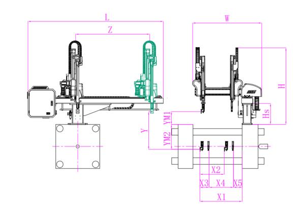
Unit: mm
| X1 | X2 | X3 | X4 | Y | YM1 | YM2 | Z | L | W | H | Payload | 1900 | 734 | 450 | 1150 | 1500 | 450 | 1050 | 2300 | 3120 | 2350 | 2400 | 15kg |
|---|
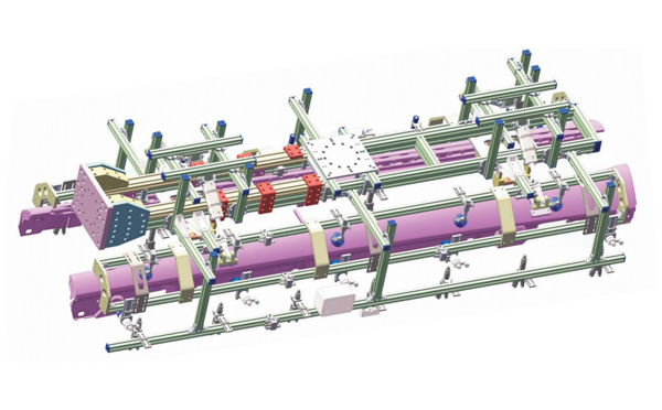
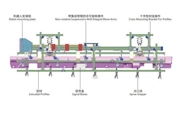
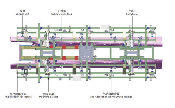
EOAT Assembly Demonstration -- One Cavity Car Threshold Strip Picking EOAT
Product Descriptions
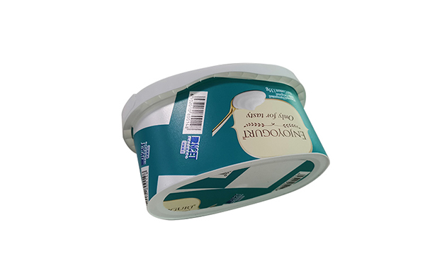
How is the SWITEK IML System for 2 Cavities Butter Box with 2 Lables Designed?
IML Containers with 2 lables will provide more space for the dairy products producers to design their pattern and provide more detailed description of their products, but with one more label it'll make the design of the IML system much more complex. How would be the two labels to be put into the mold and what would be the recommendation of such an IML system?
SWITEK has both solutions of 2 cavities IML solutions for oval shpe box and 4 cavities IML solutions for round cups with 2 labels. The difference of the 2 labels IML solutions of wrap + bottom labeling will request more space for the magazine layout design. Both the labels would be put into the cavities at the movable part of the platen with the parts to be picked from the fixed part of the platen.
Since the structure of the magazine for the IML containers with two labels is much more complex than that of wrap labeling only, the best solution is to have a turn-key IML solutions from SWITEK Automation so we can have the robot and the injection mould well tested together before delivery to ensure that the system which you received is ready to work. For more details about a turn-key IML solutions please contact Adams from SWITEK Automation, you're personal advisor of IML Soutions integration.