sales06@switek.biz

+86 186 5927 5869

Shopping

Subscrib to Us
sales06@switek.biz
+86 186 5927 5869
Shopping
Subscrib to Us
Keywords:IML Robot; IML Robot Operating; In Mold Labeling Robotics
The screen of the pendant is the interface of the IML robot from where the operator will operate and program the IML robot. In this chapter we'll introduce how to program and set the parameters of the IML robot. Below the interface of the IML robot after powering and system loading for your reference:

Toggle the knob in the upper left corner of the handset to MANU, and the interface is as follows:
(1)Axis operation
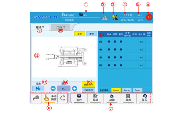
A list of the functions of each button on the screen:
| No | Name | Function |
|---|---|---|
| (1) | Current profile name | Click the name of the file currently in use to enter the file management page, and upload, download, read, save, overwrite, compare, and delete the file management. |
| (2) | Alarm display | If the alarm is currently in the alarm state, the icon is read, click to view the alarm details. |
| (3) | User level | The current user level is displayed, click to switch users 1/2/3/4 (Operator/technician/manager/highest level) and change the password of each user. |
| (4) | System time | Displays the current date and time. Click to modify the settings. |
| (5) | Speed display | Current manual speed/automatic speed display. Click to modify the speed. |
| (6) | Language display | The current system displays a language icon. Click to switch the screen display language. |
| (7) | Ribbon buttons | For other function entries, click to select View to modify. |
| (8) | Running mode display | The curreent operating mode display (Origin/manual/automatic) can be switched via the knob in the upper left corner of the teach pendant. |
| (9) | Axis operation | Enter the default axis operation page of the system, and you can switch to the (13) IO operation (14) axis display page. |
| (10) | I/O operation | Click to enter the IO operation interface, which can display the input ON/OFF status in real time, and the ON/OFF of each output point. |
| (11) | Axis representation | On the axis display interface, when you use the right button to operate the axis, you can observe the real-time status of the origin, limit, brake, current position, axis torque, and speed. |
| (12) | Axis operation buttons | Switch with the main and jib of (8) and (9) and click to move each axis. |
| (13) | Perspective switching | When the shaft is operated through (15), the angle of view is switched, and it is convenient to compare with the actual machine. |
| (14) | Speed switching | Click to switch the manual running speed, which is divided into five gears:0.1/1.0/low/medium/high, note that you cannot use the 0.1/1.0 scale to move the shaft without returning to the original point. |
| (15) | Free, manual operation | Free operation: The jog of each axis can be controlled individually by pressing the buttons. Manual operation: control each axis to move to a fixed point by pressing a button. |
(2) I/O operation
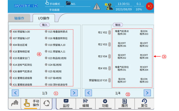
A list of each annotation function on the screen:
| No. | Name | Function |
|---|---|---|
| (1) | Page switching | Switching pages of the Input display. |
| (2) | Page switching | Switching pages of the Output button. |
| (3) | Output button | Press and hold the safety enable switch on the back of the teach pendant, and then click each button to switch the output ON/OFF. |
| (4) | Input Display | ON/OFF display of input signals. |
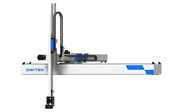
SW7730DS
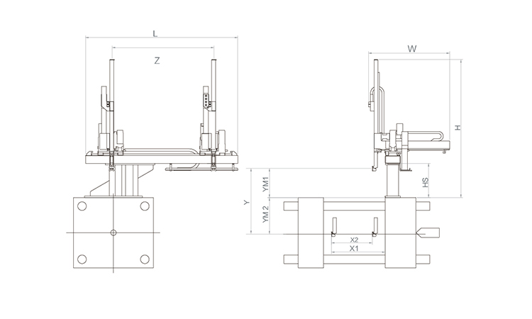
Unit: mm
| X1 | X2 | X3 | X4 | Y | YM1 | YM2 | Z | L | W | H | Payload | 2250 | 1720 | 0 | 0 | 3000 | 780 | 2220 | 4000 | 5050 | 3005 | 3440 | 75kg |
|---|
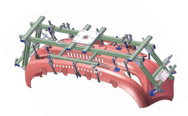
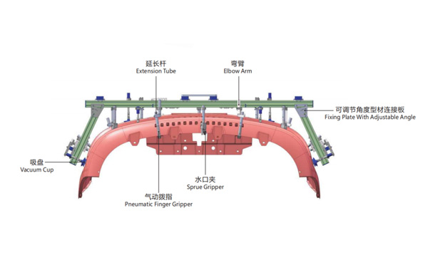
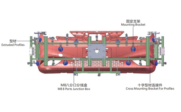
EOAT Assembly Demonstration -- One Cavity Car Bumper Picking EOAT
Product Descriptions
How is the SWITEK IML System for 2 Cavities Butter Box with 2 Lables Designed?
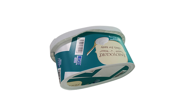
IML Containers with 2 lables will provide more space for the dairy products producers to design their pattern and provide more detailed description of their products, but with one more label it'll make the design of the IML system much more complex. How would be the two labels to be put into the mold and what would be the recommendation of such an IML system?
SWITEK has both solutions of 2 cavities IML solutions for oval shpe box and 4 cavities IML solutions for round cups with 2 labels. The difference of the 2 labels IML solutions of wrap + bottom labeling will request more space for the magazine layout design. Both the labels would be put into the cavities at the movable part of the platen with the parts to be picked from the fixed part of the platen.
Since the structure of the magazine for the IML containers with two labels is much more complex than that of wrap labeling only, the best solution is to have a turn-key IML solutions from SWITEK Automation so we can have the robot and the injection mould well tested together before delivery to ensure that the system which you received is ready to work. For more details about a turn-key IML solutions please contact Adams from SWITEK Automation, you're personal advisor of IML Soutions integration.