
sales06@switek.biz

+86 186 5927 5869

Shopping

Subscrib to Us
sales06@switek.biz
+86 186 5927 5869
Shopping
Subscrib to Us
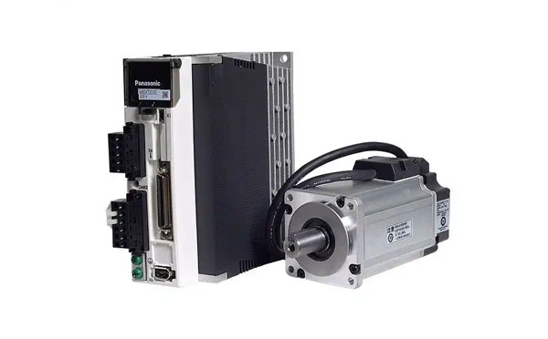
Keywords:Panasonic A6 Servo Motor, Panasonic A6 Servo Motor Driver, Panasonic A6 Servo Motor setting instruction
A routine maintenance and inspection of the driver and motor are essential for the proper and safe operation of the Panasonic A6 series motors in your injection automation system. Here in this chapter you'll have an overall idea of what's to do and not to do in the routine maintenance and inspection of the Panasonic A6 series motor and driver.
Routine maintenance and inspecdtion of the driver and motor are essential for the proper and safe operation.
Notes on Maintenance and Inspection
Inspection Items and Cycles
General and normal running condition
Ambient conditions: 30°C (annual average), load factor of 80% or lower, operating hours of 20 hours or less per day.
Perform the daily and periodical inspection as per the items below.
| Type | Cycles | Items to be Inspected |
|---|---|---|
| Daily Inspection | Cycle |
|
| Motor with Gear Reducer | Annual |
|
Note: Inspection cycle may change when the running conditions of the above change.
Guideline for Parts Replacement
Use the table below for a reference. Parts replacement cycle varies depending on the actual operating conditions. Defective parts should be replaced or repaired when any error have occurred.
 Prohibited | Disassembling for inspection and repair should be carried out only by authorized dealers or service company. |
| Product | Component | Standard Replacement Cycles (Hour) | Note |
|---|---|---|---|
| Driver | Smoothing condenser | Approx. 5 years | These hours or cycles are reference. When you experience any error, replacement is required even before this standard replacement cycle. |
| Cooling Fan | 2 to 3 years (10000 to 30000 hours) | ||
| Aluminum electrolytic capacitor (on PCB) | Approx. 5 years | ||
| Rush current preventive relay | Approx.100000 times (depending on working condition) | ||
| Rush current preventive resistor | Approx. 20000 times (depending on working condition) | ||
| Motor | Bearing | 3 to 5 years (20000 to 30000 hours) | |
| Oil seal | 5000 hours | ||
| Encoder | 3 to 5 years (20000 to 30000 hours) | ||
| Battery for absolute encoder | Life time of battery read P7-14 please |
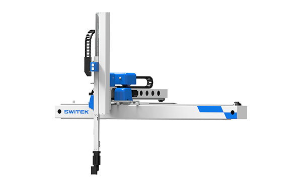
SW7112DS
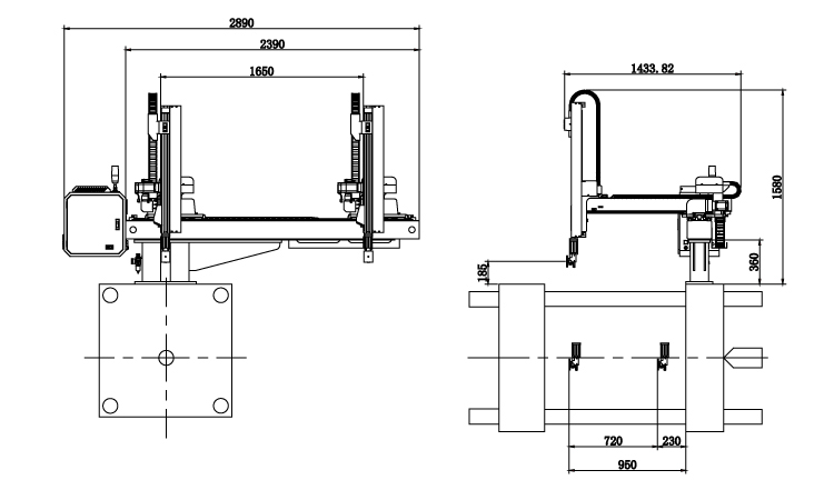
Unit: mm
| X1 | X2 | X3 | X4 | Y | YM1 | YM2 | Z | L | W | H | Payload | 950 | 720 | 0 | 0 | 1200 | 425 | 775 | 1650 | 2710 | 1434 | 1780 | 5kg |
|---|
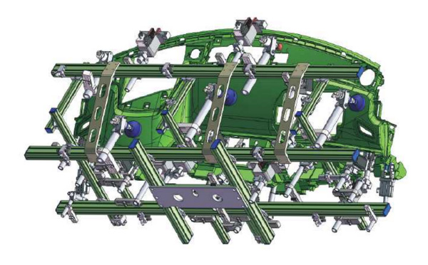
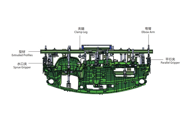
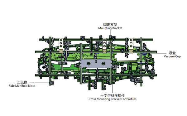
EOAT Assembly Demonstration -- One Cavity Instrument Panel Picking EOAT
Product Descriptions
For Thin Wall Container IML Production, Will YIZUME P250E or P250K3 a Better Choice for Your Project?
As for which injection molding machine is a better choice for your IML project, it'll depends on your budget and requirement about the parts. As we know both P250E and P280K3 are excellent high speed injection molding machine designed for the injection production of thin wall containers with high injection speed for the fast injection of thin wall containers. They're no dobt excellent injection molding machine for your IML project. But, how to make a decision between?
Both P250E and P250K3 has similar injection speed (300/500 mm/s optional for P250E and 320mm/s for P250K3) but P250E is an all electric injection molding machine while P250K3 is a high speed hydraulic injection molding machine. Of course an all electric injection molding machine is a better choice for food container IML production, but, the cost of it would be much higher than P250K3. So, if your budget is sufficient, P250E, if not, P250K3 would be the right one for you.
The IML robot for YIZUMI P250K3/P250E would be SWITEK IML Robot SW833. In K2019 SWITEK IML robot SW833 work with P250E in demo of 4 cavities cups at the cycle time of 2.1s, this combination is one of the best IML solution for small size containers IML production.


