
sales06@switek.biz

+86 186 5927 5869

Shopping

Subscrib to Us
sales06@switek.biz
+86 186 5927 5869
Shopping
Subscrib to Us
Keywords:Panasonic A6 Servo Installation Instruction, Panasonic A6 Driver, Panasonic A6 Series Servo Motor Manual
Here in this chapter is the wiring instruction of input/out connecting to the contacts of switches and relays, or open collector output transistors.
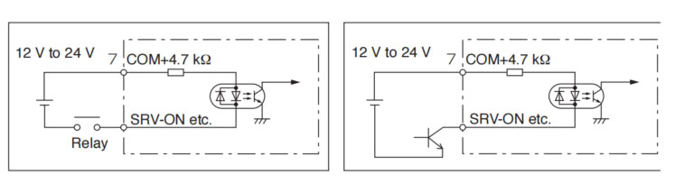
| VDC | Specifications |
| 12V | 820 Ω 1/2W |
| 24V | 2 kΩ 1/2W |
| (VDC - 1.5)/(R+220) = 10mA | |
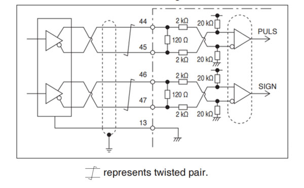
Line driver I/F (Permissible max. input frequency of command pulse input signal.: 8 Mpulse/s)
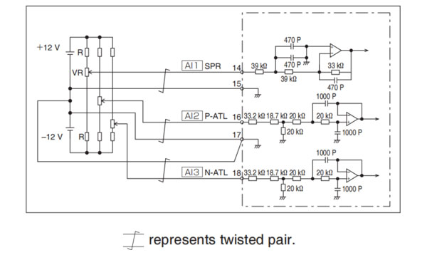
Only for the standard type and communication type are not provided with analog input.

SW6310D-20
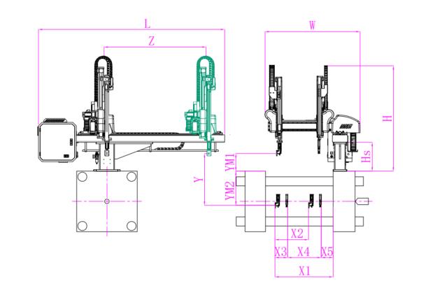
Unit: mm
| X1 | X2 | X3 | X4 | Y | YM1 | YM2 | Z | L | W | H | Payload | 740 | 640 | 140 | 415 | 1000 | 235 | 765 | 1650 | 2640 | 1500 | 1580 | 3kg |
|---|
EOAT Assembly Demonstration -- One Cavity Instrument Panel Picking EOAT
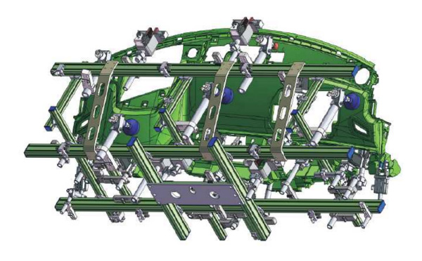
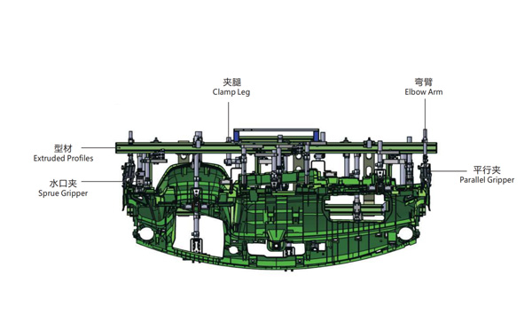
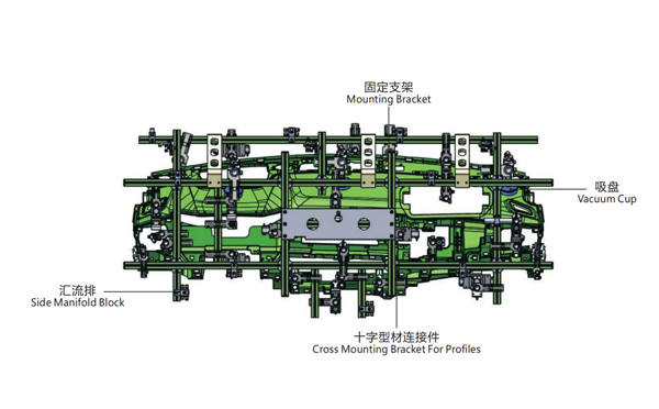
Product Descriptions
YIZUMI P350 or P380K3, which one would be a better choice for your IML project?
P350 is a high speed injection molding machine designed for thin-wall containers while P380K3 is the third generation of high speed injection molding machine by YIZUMI designed for thin-wall containers. With 30 Tons more in clamping force, does it mean that P380K3 will compatible to the molds designed according to the parameters of P350?
In one just finished IML project we encountered something embrassing. There's one mold designed according to the parameter of YIZUMI P350, and we have a P380K3 in our system testing workshop, but when the mold received we find that the mold thinkness exceeded the max mold thickness of the P380K3. After double check the parameters of both the injection molding machine we found that Mold thickness allowed for P350 is 300~750mm while the mold thickness for P380K3 is only 250~650mm. And the Max Daylight of P380K3 is 160mm less than P350.
Then how to choose between, which one would be a better choice for your IML project? It would be depends on the size of the parts of which you're producing. For smaller container 30 Tons more clamping force with 160mm less max daylight means that the injection molding machine will have a less mold Open/Close time and result in a higher productivity while for larger size containers P350 will allow you to install a thicker mold, it would be more friendly to an IML project of deep cavity containers.
For more insights of the cutting edge IML technology please feel free to contact Adams from SWITEK, your personal consultant of IML Solutions.


