
sales06@switek.biz

+86 186 5927 5869

Shopping

Subscrib to Us
sales06@switek.biz
+86 186 5927 5869
Shopping
Subscrib to Us

Keywords:IML Robot; IML Robot Operating; In Mold Labeling Robotics
"Teaching" is where for you to review and edit the program of the IML robot. As a modular designed control system, after the mode selecting, parameters setting, timer setting, counter setting, you'll get an initial program for your IML project. In "Teaching" page you can do some minor adjustment of the program to have the IML robot working more efficiently.
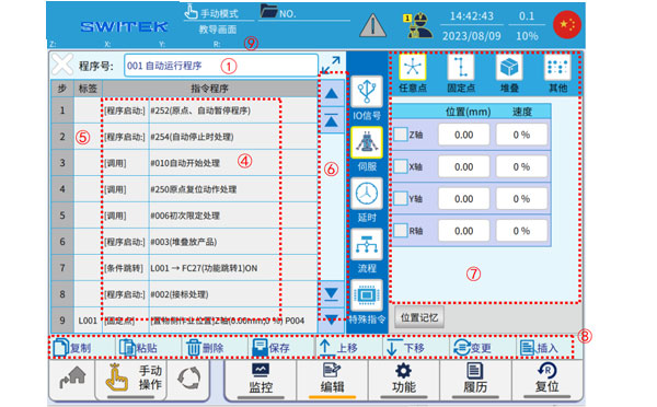
Description of each marking area:
| No. | Name | Function |
|---|---|---|
| (1) | Program Select/Display | Click the pop-up "Program List", select the program number you want to add, edit, or view, and click to enter the editing interface. |
| (2) | Program extension display | Click  , enter the extended interface of the program display for easy observation of the complete command content. , enter the extended interface of the program display for easy observation of the complete command content. |
| (3) | Return | Click to exit the tutorial editing interface, if the program has been changed, it will prompt compilation. |
| (4) | Instruction content | The content of the command is displayed. |
| (5) | Label Column | Jump to the editing area of the tab. Click to add a label before the command line (when creating a new label, you can click "EN" without entering a number, and an unused label number will be automatically added). |
| (6) | A first-level list of instructions |
|
| (7) | Command secondary list and parameter settings | Sub-list command editing and parameter setting. |
| (8) | Command editing shortcuts |
|
| (9) | Axis position display | The current position of each axis is displayed for easy observation. |
Below details of how to "Teach" an IML Robot Program:
Click on the program name display area to enter the program list.
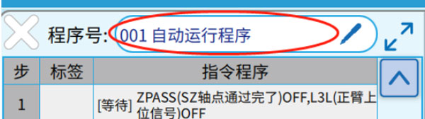
The interface is as follows:
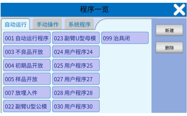
Autorun (001-099): 001 is the main program that can be edited by the user, 024-083 are user-created and edited subroutines.
Manual operation (#178-#249):
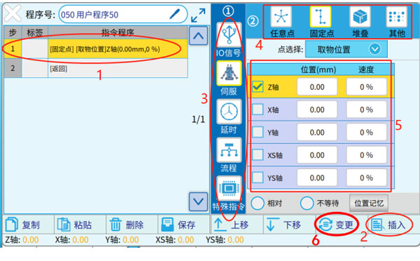
The editing interface is as shown in the figure above, and the new command line is divided into the following 6 steps:
Below are some of the most commonly used commands:
When teaching application programming, it's not recommended that users edit the basic X and Y point logic for the standard IO control of the injection molding machine and manipulator (IML Robot here), and should call the function subroutine of the system to ensure the accuracy of the program. These subroutines are placed in the "IO Signals" class.
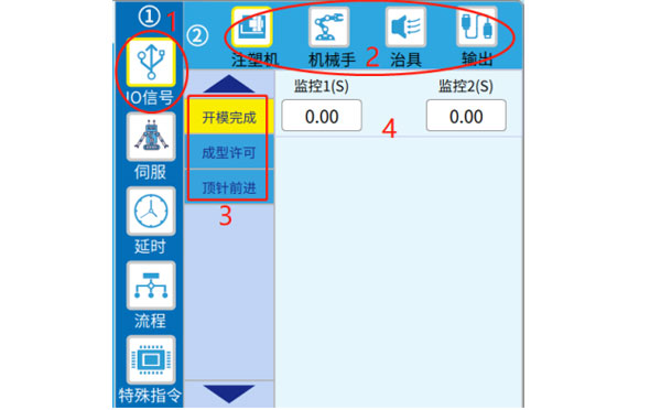
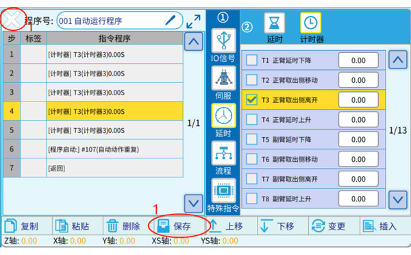
As shown in the figure above, the programming steps are set step by step according to 1 (Major category), 2 (sub-catgeory), 3 (Specific instructions), and 4 (Specific parameters), and after the completion, click "Change" or "Insert".
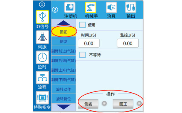
When editing the convenience functions related to the IML robot, you can use the buttons in the following figure to operate the IML robot related jigs (You can observe the ON/OFF of the sensing signal by turning the dot on or off on the right  ), it is convenient to program simulations in real-world operating scenarios.
To edit the output logic of the I/O point, the editing interface is as follows:
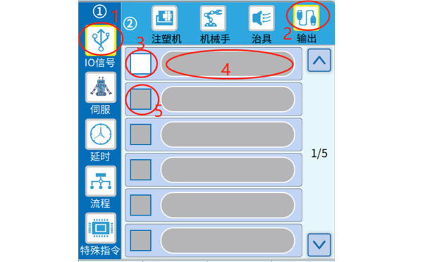
In the editing interface of the above figure, click on the label number 3 to √, mark 4 becomes editable, select the Y point ON or OFF to be output, and confirm. If you want to output IML robot Y-points at the same time, at designator 5, √ to start editing the output of the second Y-point. When you're done, click "Change" or "Insert".
Edit the movement commands of the servo axis, including moving to a fixed point (the point is defined, can be modified in the "Position Setting", and can be referenced), any point, stacked point (the position is set in the "Stack" in the menu), and the axis back to origin command, etc. Take a fixed point as an example:
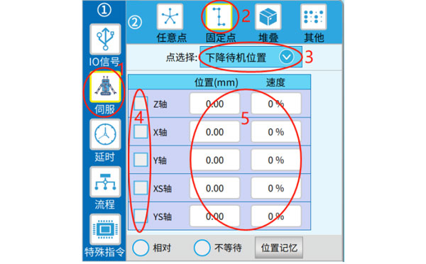
As shown in the figure above, select the specific point at label 3, then select the axis to run at label 4, and set the point and speed at label 5. When you're done, click "Change" or "Insert".
There are two types of editing delay commands: specifying the time and specifying the timer (the timer time can be changed when it runs automatically).
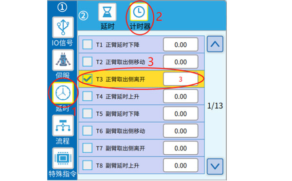
Note: If you want to use a timer when teaching programming, prefer the T85-T100, which are user timers that are not specifically defined.
Invocation and program startup are both ways of using subroutines. The difference is that when a subroutine is called, it waits for the execution of the instruction in the subroutine to end (to the "return" instruction), and the call is considered complete, and the next instruction can be executed in the main program. On the other hand, you do not need to wait for the startup subprogram to be executed, and you can directly start the next step of the main program (the main program and the subprogram are executed in parallel).
The steps to edit the program startup command are as follows:
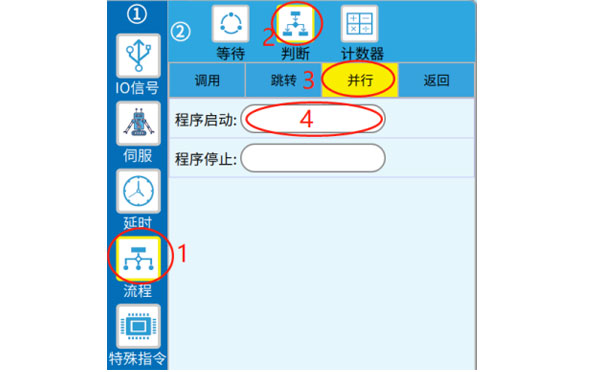
Note: The program starts the open subprogram, which can be closed by "Program stop" above (under normal circumstances, the subprogram will be automaticall closed after the execution is completed and the "return" instruction is reached).
The steps to edit the invocation command are as follows:
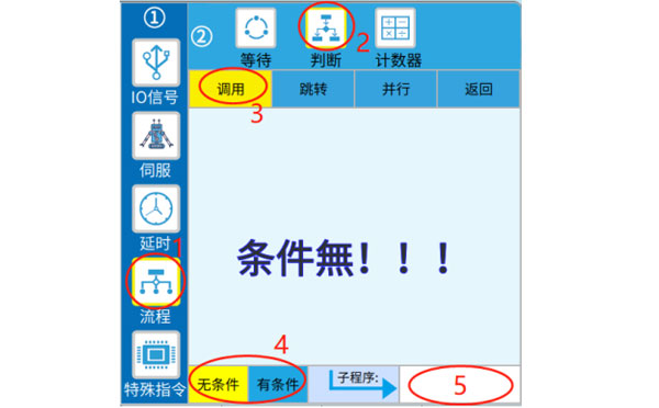
As shown in icon number 4 above, when editing the call instruction, you can choose whether to set the condition, select "unconditional", and then set the subroutine number to be called at mark 5 to complete the call. If you select "Conditional", you need to complete the condition setting first, then set the program number at 6 labels, and click "Change" or "Insert"
Note that when the previous conditional judgement is not true, the subsequent call will not be executed, but the next line of instructions will be started.
Jump command: The program is executed to the jump command, and the next step will execute the command line with the corresponding tag, instead of executing it in the next order.
Jump/conditional jump, the command editing steps are as follows:
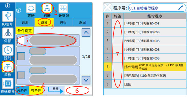
Select whether you want to set conditions in label 4, set conditions in label 5 (you can set multiple conditions), set label numbers in label number 6, and select "Change" or "Insert" to generate commands. Then fill in the label column shown in label number 7, before the target command line.
If a "conditional" jump is used, the previous condition judgement is not valid, and the subsequent jump is not executed, and the next line of instructions will be started directly. If the condition is true, run the command line that jumps to the label.
The output of the internal flag is ON/OFF, and the editing procedure is shown in the icon number below.
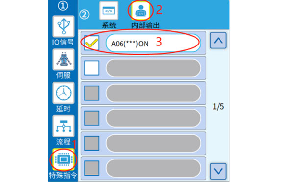
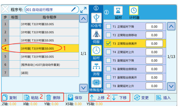
As shown in icon number 1 above, select the command line you want to edit (turn yellow) and then use the button at label 2 to perform the operation.
The functions of each button are as follows:
When the program is edited, you can click "Save" or " " or jump to other settings pages to trigger the "Compilation" prompt, click "Yes", and wait for the editing to complete (it will be automatically saved after compilation).
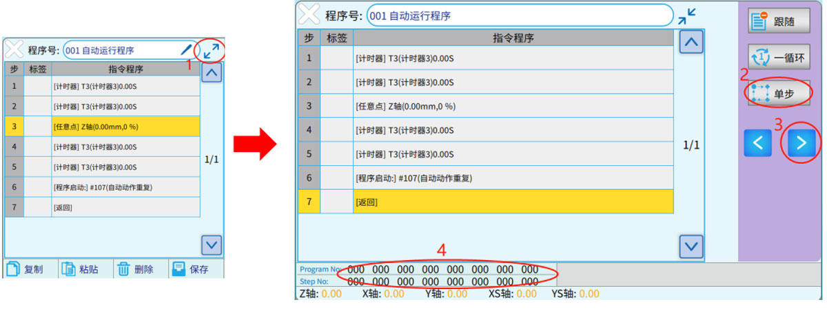
Toggle the know in the upper left corner of the teach pendant to AUTO enter the automatic operation interface. Go to the teaching, as shown below, and click on the " " icon shown in label 1, enter the extended display screen. Click label 2 "Single step" to enter the single step state, press the label 3 " " button once, and the program will go down to 1 step.
The progress of the program can be viewed at number 4, "Program No" is the number of the program being executed, and "Step No" is the number of the program being executed.

SW6715D
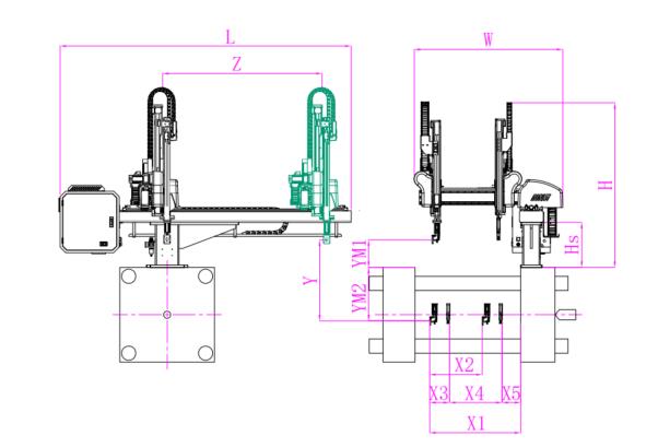
Unit: mm
| X1 | X2 | X3 | X4 | Y | YM1 | YM2 | Z | L | W | H | Payload | 1900 | 734 | 450 | 1150 | 1500 | 450 | 1050 | 2300 | 3120 | 2350 | 2400 | 15kg |
|---|
EOAT Assembly Demonstration -- Two Cavities Non-woven Fabric In Mold Insertion
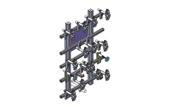
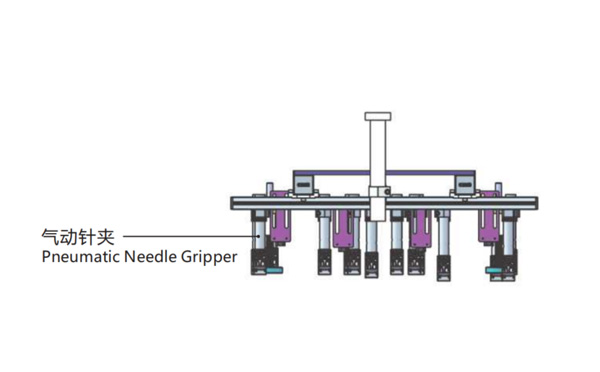
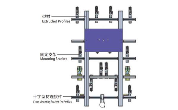
Product Descriptions
Bom List
| Product Name | PN # | Model | Quantity |
|---|---|---|---|
| Extruded Profiles | 4.Y00052 | PEP4040-1000 | 2 |
| Plugs for Profile | 4.Y00072 | PEP4040 | 4 |
| Extruded Profiles | 4.Y000481 | PEP2525-1500 | 2 |
| Extruded Profiles | 4.Y00481 | PEP2525-1000 | 1 |
| Plugs for Profile | 4.Y00070 | PEP2525 | 10 |
| Cross Mounting Bracket for Profiles | 7.Y00356-T | SMBA-2540T | 10 |
| Pneumatic Needle Gripper | 8.Y00025 | GN2010 | 14 |
| Mounting Bracket | 7.Y00308-T | SMBE2-2060T | 14 |
| Mounting Bracket | 7.Y00309-T | SMBE2-3060T | 1 |
What's a Smart Factory and How Would a Smart Factory Designed?
With the increasing labour cost globally, more and more injection molding factory owners are looking for solutions of a smart factory. But what would be a smart factory looks like and how to design a smart factory? The newly posted video of Haitian group in their Youtube account is a good reference of what would be a smeart factory.
In the video above we can find something in comman of what a smart factory would be. First of all there's a centralized feeding system from which the material for all the injection molding machines are delivred; In this factory all the parts produced are collected and transported to another workshop via a conveyor. What would be in behind these injection molding machines and conveyors to support the running of the smart factory?
The MES system (Manufacturing Execution System) would be a vital part of a smart factory which will monitor the production process of the parts, just in time mangaement of the machineries, products quality control and resources following up. The samrt factory would be smart solution to help the factory owners to reduce the labour cost.
Although sounds great, but the smart factory is not as suitable for the small and medium size producers whom will change the mould frequently. As an information technology based production, the smart factory is an integration of the software and the hardware. It may be easy to change the parameter of the software, but would be a nightmare to have the hardware changed to match the new system.
Cooperating with LESSO group in building up their smart factory for pipe fittings production, SWITEK is experienced in supply robots with protocol for MES and other smart factory system. For more details about the injection robot for the smart factory sytem, please contact Adams from SWITEK, your personal consultant of injection robot selection.


