sales06@switek.biz

+86 186 5927 5869

Shopping

Subscrib to Us
sales06@switek.biz
+86 186 5927 5869
Shopping
Subscrib to Us
Keywords:IML Robot; IML Robot Operating; In Mold Labeling Robotics
With the IML control system designed "Easy to operate", we can program the robot by selecting the standard programs and have it inserted into the program step by step. Here in this chapter we're introducing the setting of the axis positions of the IML robot.
Position setting
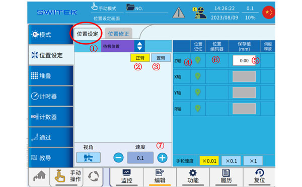
| No | Name | Function |
|---|---|---|
| (1) | Position selection | Click to select the point you want to set. |
| (2) | Main-arm selection | Click to switch to the two axes of the main arm, and cooperate with the button (7) to move the axis. |
| (3) | Sub-arm selection | Click to switch to the two axes of the jig, and cooperate with the button (7) to move the shaft. |
| (4) | Current position memory | Click the icon to set the current position of the axis to the point (after returning to the original point). |
| (5) | Point set point | (1) select the point and set the value. Click to make a changes. |
| (6) | Current axis position | The current position of the axis is displayed. |
| (7) | Manual speed setting | Manual speed setting |
Steps to set the point:
Position corrections
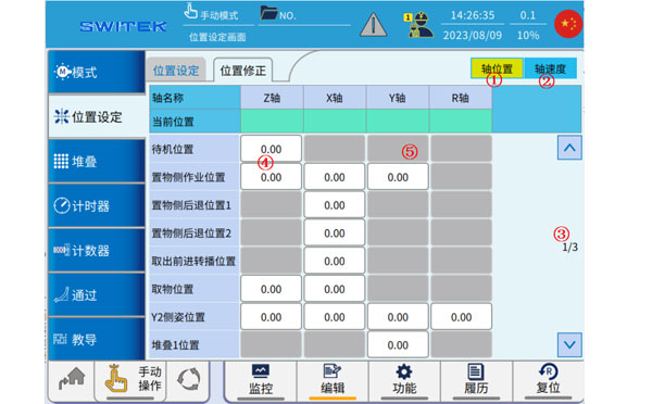
| No | Name | Function |
|---|---|---|
| (1) | Axis position | Automatically click to switch to the axis position modification |
| (2) | Axis Speed | Automatically click to switch to the axis speed modification |
| (3) | Page | Flip up and down to switch points |
| (4) | Position (Modifiable) | The white point can be clicked automatically for fine-tuning. |
| (5) | Position (not modifiable) | Gray point, cannot be modified |
This page is mainly used for an overview of the points set by the location, and when it is automatic, you can click on the point at (4) to fine-tune it.

SW6308-20
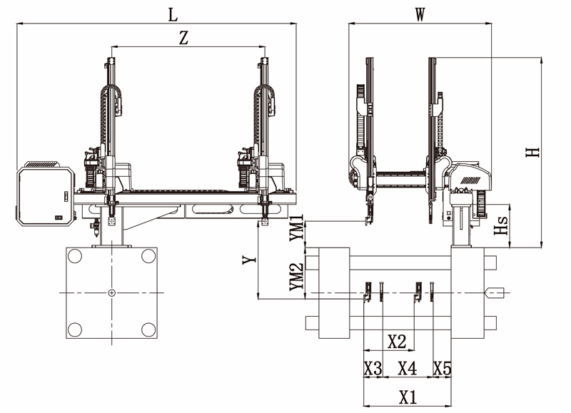
Unit: mm
| X1 | X2 | X3 | X4 | Y | YM1 | YM2 | Z | L | W | H | Payload | 980 | 640 | 165 | 645 | 800 | 235 | 565 | 1280 | 2320 | 1500 | 1690 | 3kg |
|---|
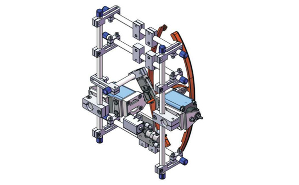
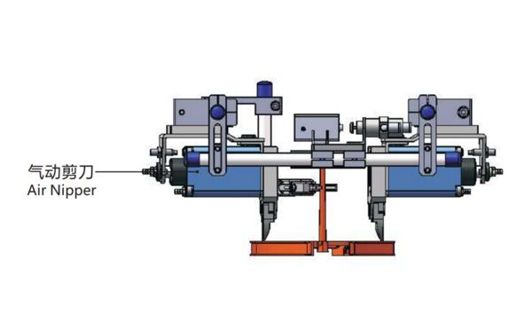
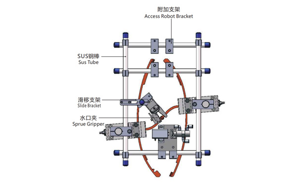
EOAT Assembly Demonstration -- Two Cavities Parts Picking EOAT with Runner Cutting by Air Nipper
Product Descriptions
Bom List
| Product Name | PN # | Model | Quantity |
|---|---|---|---|
| Sus Tube | 4.Y00021 | PST12-1500 | 2 |
| Air Nipper | 1.Y00004 | GT-NY25 | 2 |
| Straight Blades for Plastic | 1.Y00037 | NY25AJ | 2 |
| Fixing Block | 7.Y00633 | SCE2-25 | 2 |
| Tube Plugs | 1.Y03638 | PST12-1500 | 11 |
| Cross Connector | 7.Y00027 | SMBT-2012 | 2 |
| Access Robot Bracket | 7.Y00002 | SMBH1-12M6 | 6 |
| L-Type Thread Hose Fitting | 1.Y02809 | APL6-M5 | 3 |
| Slide Bracket | 7.Y00004 | SCF4-1240W16 | 7 |
| Slide Bracket | 7.Y00001 | SMBS-12T16 | 7 |
| Sprue Gripper | 8.Y00091 | GR12-12-CN | 1 |
| Cross Connector | 7.Y00020 | SMBT-1212 | 1 |
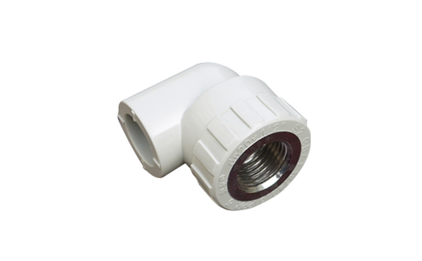
Why is 8 Cavities Mold Design the Best Solution for Elbow with Nuts?
For PVC/PPR pipe fittings with nuts with a diameter of around φ25mm most of the producer will choose an injection molding machine of around 250T and a mold cavities of 8 Cavities, will a more cavities mold design with a larger injection molding machine a better choice for pipe fittings producers?
According to the experience of working with LESSO group in the automiztion of their PVC/PPR pipe fittings injection production system, we finally decide to have an 8 cavities mold deisgn with 250T injection molding machine because:
Anyway, to upgrade your PVC/PPR pipe fittings injection molding system you must keep in mind that it's only valuable to have an automation system for bulk production products, which means that one injection molding machine with only one mold to be equipped with one automation system for the pipe fittings' Nut insertion, runner cutting and parts picking.
For any other question about a PVC/PPR pipe fittings auto-production system please contact Adams from SWITEK for a turn-key solutions of pipe fittings production.