
sales06@switek.biz

+86 186 5927 5869

Shopping

Subscrib to Us
sales06@switek.biz
+86 186 5927 5869
Shopping
Subscrib to Us
Keywords:IML Robot; IML Robot Operating; In Mold Labeling Robotics
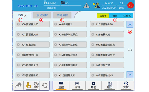
The "Monitor" which we're discussing here is where you'll have a clear understanding of the working stituation of the robotic arm. In monitor page you can check the signal of the robotic arm, the EOAT, the injection molding machine and the working status of the servo motor and the control system of the IML robot for a fast diagnose of the broken point of the system.
Click  icon, the following page pops up the monitoring page:
| No | Name | Function |
|---|---|---|
| (1) | Robot/Jig/IMM | IO displays the category, click to quickly switch to the corresponding signal page. |
| (2) | Page | Click to switch to the I/O page |
| (3) | IO display | Real-time ON/OFF display of all current input and output points. |
| (4) | Drive monitoring | Real-tme display of speed, torque, load rate, and deviation of each axis servo motor. |
| (5) | Internal monitoring | Real-time display of internal I/O status. |
Use (1) or (2) to switch the IO display, and the front light is on to indicate that the signal is on.
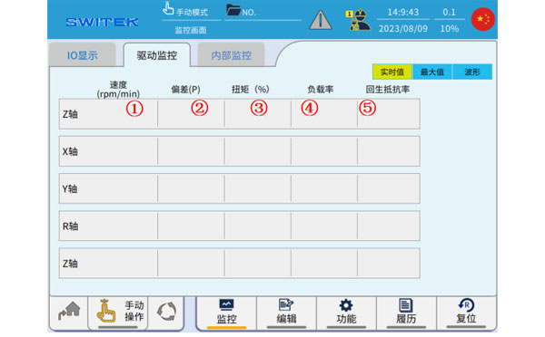
3.5.2 Drive monitoring
Real-time values
| No | Name | Function |
|---|---|---|
| (1) | Speed (rpm/min) | Real-time display of the running speed of each axis. |
| (2) | Deviation (P) | Real-time display of deviations in each axis. |
| (3) | Torque (%) | Real-time percentage display of torque for each axis. The instantangeous torque of the servo motor can reach up to 300% of the rated torque. |
| (4) | Load factor | Real-time display of the operating load factor of each axis. (100% max) |
| (5) | Resilience resistance rate | Real-time display of the load rate of respawn resistance. |
Maximum

| No | Name | Function |
|---|---|---|
| (1) | Forward Maximum Speed | A record of the maximum speed of each axis as it moves in the positive direction. |
| (2) | Negative maximum speed | A record of the maximum speed of each axis moving in a negative direction. |
| (3) | Positive maximum deviation | Records the maximum deviation of each axis in the positive direction. |
| (4) | Negative maximum deviation | A record of the maximum deviation of each axis in the negative direction. |
| (5) | Forward maximum torque | A record of the maximum torque of each axis as it moves in the positive direction. |
| (6) | Negative maximum torque | A record of the maximum toruqe of each axis when it moves in the negative direction. |
| (7) | Reset | The maximum value previously recorded is cleared. |
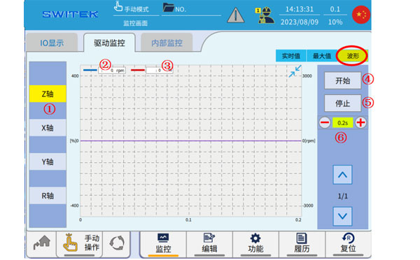
Waveform
| No. | Name | Function |
|---|---|---|
| (1) | Axis selection | Click to select the axis to display. |
| (2) | Torque (%) | The blue waveform curve shows the change in torque. The instantaneous torque of the servo motor can reach up to 300% of the rated torque. |
| (3) | Speed(rpm/min) | The red waveform curve shows the change in velocity. |
| (4) | Start | After selecting the (1) axis, click "Start" to start the waveform sampling. |
| (5) | Stop | Stop waveform sampling |
| (6) | The waveform displays the scale. | Click "+" and "-" to zoom in and out of the displayed waveform. |
3.5.3 Internal Monitor
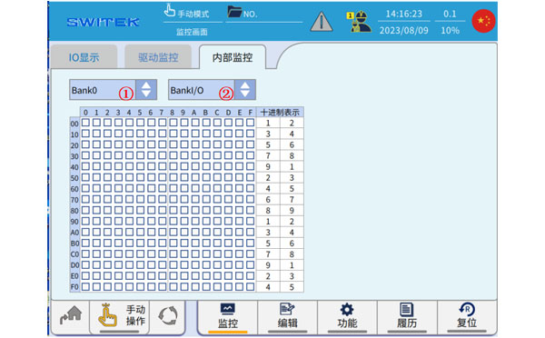
"Internal monitoring" refers to the monitoring of the ON/OFF of the internal flag position of the controller, which is divided into 5 blank *2 units, a total of 10 areas, and the switching between bank and unit is completed through (1) and (2).
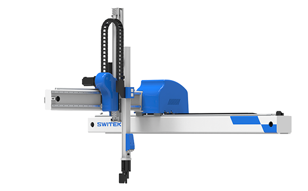
SW6715DS
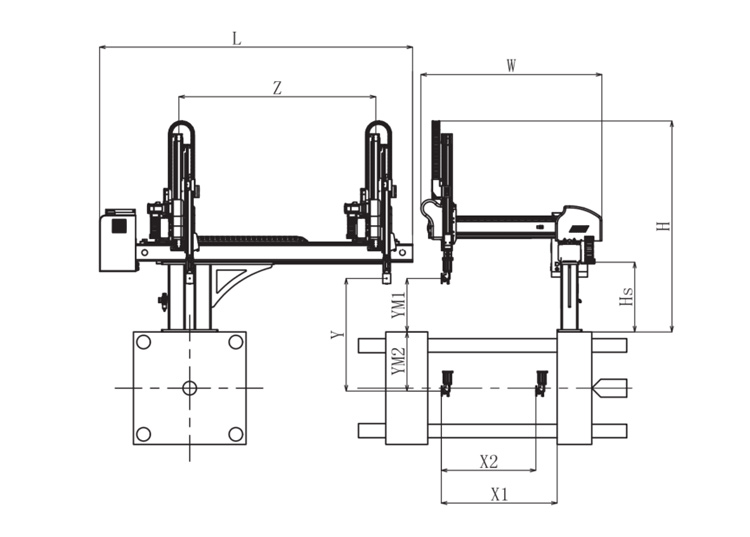
Unit: mm
| X1 | X2 | X3 | X4 | Y | YM1 | YM2 | Z | L | W | H | Payload | 1400 | 1180 | 0 | 0 | 1500 | 480 | 1020 | 2500 | 3120 | 2200 | 2400 | 15kg |
|---|
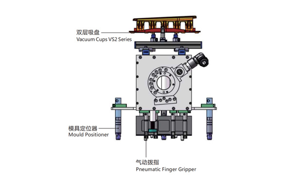
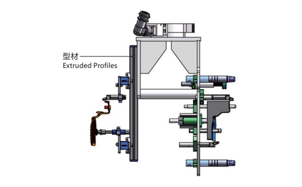
EOAT Assembly Demonstration -- One Cavity In Mold Insertion EOAT With Mold Positioner
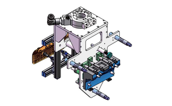
Product Descriptions
Bom List
| Product Name | PN # | Model | Quantity |
|---|---|---|---|
| Extruded Profiles | 4.Y00481 | PEP2525-1500 | 1 |
| Plugs for Profile | 4.Y00070 | PEP2525 | 8 |
| Mould Positioner | 8.Y00088 | GMP20A | 3 |
| Vacuum Cups VS2 Series | 1.Y05310 | VS2-SA20 | 2 |
| Rotative Suspensions | 8.Y00061 | VFR1421-G18 | 2 |
| Pneumatic Finger Gripper | 8.Y00084 | GFR14-95G | 7 |
| Extension Tube | 7.Y00733 | SMBY14-50 | 6 |
| Mounting Bracket | 7.Y00200-T | SMBE1-1440T | 3 |
| Cross Mounting Bracket for Profiles | 7.Y00194-T | SMBA-2525T | 4 |
| Vacuum Cup Fittings | 7.Y00703 | VM02-G18 | 2 |
YIZUMI P350 or P380K3, which one would be a better choice for your IML project?
P350 is a high speed injection molding machine designed for thin-wall containers while P380K3 is the third generation of high speed injection molding machine by YIZUMI designed for thin-wall containers. With 30 Tons more in clamping force, does it mean that P380K3 will compatible to the molds designed according to the parameters of P350?
In one just finished IML project we encountered something embrassing. There's one mold designed according to the parameter of YIZUMI P350, and we have a P380K3 in our system testing workshop, but when the mold received we find that the mold thinkness exceeded the max mold thickness of the P380K3. After double check the parameters of both the injection molding machine we found that Mold thickness allowed for P350 is 300~750mm while the mold thickness for P380K3 is only 250~650mm. And the Max Daylight of P380K3 is 160mm less than P350.
Then how to choose between, which one would be a better choice for your IML project? It would be depends on the size of the parts of which you're producing. For smaller container 30 Tons more clamping force with 160mm less max daylight means that the injection molding machine will have a less mold Open/Close time and result in a higher productivity while for larger size containers P350 will allow you to install a thicker mold, it would be more friendly to an IML project of deep cavity containers.
For more insights of the cutting edge IML technology please feel free to contact Adams from SWITEK, your personal consultant of IML Solutions.


