sales06@switek.biz

+86 186 5927 5869

Shopping

Subscrib to Us
sales06@switek.biz
+86 186 5927 5869
Shopping
Subscrib to Us

Keywords:IML Robot; IML Robot Operating; In Mold Labeling Robotics
The mechanical parameters setting of the IML robot include the selection of the modular of the function unit, the mechanical parameter of the axis, the servo motor etc. to ensure that the IML robot is working safely and efficiently.
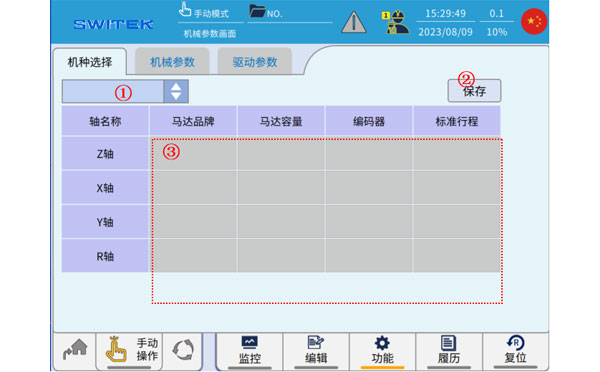
Model Selection
| No. | Name | Function |
|---|---|---|
| (1) | Model selection | Click here to select the applicable mode name. |
| (2) | Save | After selecting (1) the model, click "Save" to confirm the operation. |
| (3) | The information of the selected model is displayed | The section of the information is displayed for the models to help you distinguish between them. (This part of the information in the model needs to be maintained during producdtion to maintain accuracy.) |
Please note that the above operation, model selection - saving, after the completion of the model content does not take effect immediately, need to be initialized in mechanical parameters, servo parameters - saving, and then the system restarts, will take effect.
Mechanical Parameters
| No. | Name | Function |
|---|---|---|
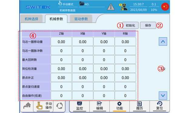
| (1) | Initialize | Clicking on it will read the initial data of the mechanical parameters in the model file and feedback it to the display at (4). |
| (2) | Save | Save existing changes |
| (3) | Page | Parameters are scrolled up and down. |
| (4) | Mechanical Parameter content |
|
Please note that the modification of the above parameters does not take effect immediately, but needs to be saved, and will only take effect after the system restarts.
Drive parameters
| No. | Name | Function |
|---|---|---|
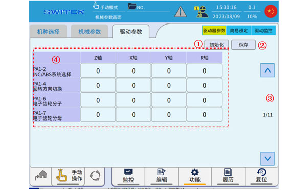
| (1) | Initialize | Clicking on it will read the initial data of the drive parameters in the model file and feedback it to the display at (4). |
| (2) | Save | Save existing changes. |
| (3) | Page | Parameters are scrolled up and down. |
| (4) | Drive parameter content | Each driver parameter is edited and displayed. |
Instructions for setting some drive parameters:
| No. | Name | Effect | Initial Value | Range | Unit | The main point of the setting | |
|---|---|---|---|---|---|---|---|
| PA1-02 | INC/ABS System selection | Reboot | 0 | 0~1 | "0" is an incremental motor, "1" is an absolute motor | ||
| PA1-04 | Direction of rotation | Reboot | 0 | 0~1 | Adjust when the motor rotates in the wrong direction | ||
| PA1-13 | Tuning mode | Realtime | 0 | 0~2 | 0 is automatic, 1 semi-automatic, 2 manual. The robot is set to 1 when it is shipped. | ||
| PA1-14 | Load-to-torque ratio | Realtime | 23.0 | 0.0~300 | Times | ||
| PA1-15 | Tuning gain | Realtime | 7 | 1~40 | |||
| PA1-27 | Forward torque limit value | Realtime | 300 | 0~500 | |||
| PA1-28 | Negative torque limit value | Realtime | 300 | 0~500 | |||
| PA1-52 | S acc/dcc setting | Realtime | 0.0 | 0.0~1000.0 | |||
| PA1-54 | A fixed number of position command answers | Realtime | 30.0 | 0.00~250.00 | |||
| PA1-55 | Position Ring Gain 1 | Realtime | 17 | 1~2000 | |||
| PA1-56 | Speed Ring Gain 1 | Realtime | 5 | 1~2000 | |||
| PA1-58 | Feedback Gain 1 | Realtime | 0.000 | 0.000~1.500 | |||
| PA1-59 | Torque filtering | Reboot | 0.00 | 0.00~20.00 | |||
| PA1-70 | Notch filter mode | Realtime | 1 | 0~1 | When 0, the automatic detection 1 is valid for the set value | ||
| PA1-71 | Notch 1 frequency number | Realtime | 134 | 10~4000 | |||
| PA1-72 | Notch 1 attenuation | Realtime | 1 | 0~40 | |||
| PA1-73 | Notch 1 width | Realtime | 2 | 0~3 | |||
| PA1-74 | Notch 2 frequency number | Realtime | 53 | 10~4000 | |||
| PA1-75 | Notch 2 attenuation | Realtime | 1 | 0~40 | |||
| PA1-76 | Notch 2 width | Realtime | 2 | 0~3 | |||
| PA1-78 | The frequency number 0 of the braking anti-resonance | Realtime | 7.0 | 1~300.0 | Hz | Vibration suppression is effective when stopping, and it is necessary to measure the actual vibration before setting. | |
| PA1-79 | Brake vibration inertia ratio | Realtime | 0 | 0~80 | If it is set to 0, PA1-78 will be invalid, and when it is set to 1, PA1-78 will be valid. | ||
| PA1-80 | The frequency number 1 of the braking anti-resonance | Realtime | 8.0 | 1~300.0 | Hz | Vibration supression is effective when stopping, and it is necessary to measure the actual vibration before setting. | |
| PA1-81 | Brake vibration inertia ratio | Realtime | 0 | 0~80 | If it is set to 0, PA1-80 is invalid, and when it is set to 1, PA1-80 is valid. | ||
| PA1-94 | Torque filter mode | Reboot | 0 | 0~1 | Set to 0 and do not use torque filtering | ||
| PA2-64 | Brakek action time | Realtime | 0 | 0.00~99.9 | Sec | ||
| PA2-65 | Retrograd resistance selection | Reboot | 1 | 0~1 | Set 1 when the regeneration resistor is connected, and 0 when not connected | ||
| PA2-69 | Deviation over detected value | Realtime | 15.0 | 0.1~100.1 | Rev | ||
| PA3-79 | Retrograde impedance value setting | Realtime | 30.0 | 3.9~160.0 | Ω | The value of the regenerative resistance is set | |
| PA3-80 | Respawn impedance power setting | Realtime | 40 | 1~5000 | W | Retroactive resistance capacity setting | |
Easy set-up-tuning mode
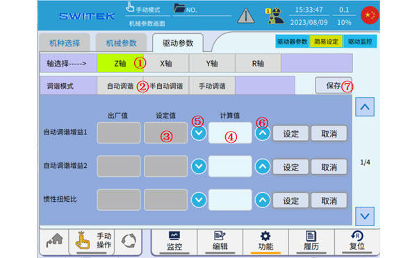
| No. | Name | Function |
|---|---|---|
| (1) | Axis selection | Click to select the axis you want to work on. |
| (2) | Auto-tune | When the machine is adjusted before leaving the factory, the drive parameters can be deduced in this mode. |
| Semi-automatic tuning | Semi-automatic tuning mode, some parameters are fixed, and some parameters will be fine-tuned. | |
| Manual tuning | All drive parameters are fixed. | |
| (3) | Set value | The tuned gain, to-inertia-to-torque ratio currently in use. |
| (4) | Calculated value | The value derived from the current calculation. |
| (5) |  | Apply the Calculated Value content to the Set Value. |
| (6) |  | Apply the contents of the "Set Value" to the "Calculated Value". |
| (7) | Save | Modify and save the current driver parameters. |
When automatic, you can switch the tuning mode of each axis on this interface, modify the inertia-torque ratio and tuning gain, so as to observe the operation effect of the set values in real time and find more reasonable parameter settings.
When set to auto-tuning mode, the parameter PA1-14 inertia-torque ratio is measured in real time.
The main function of the automatic tuning mode is to automatically adjust the value according to the running effect when the appropriate driving parameters are not know at the initial stage of debugging, until the running effect is good and stable, and the inertia-torque ratio value will tend to be constant.
When the running effect is stable, switch to the semi-automatic tuning mode, manually set the parameters, save them, turn off the power and restart them again before the parameters are effective. In the semi-automatic tuning mode, the main parameters such as the "inertia torque ratio" will be fixed, and some servo parameters will still be adjusted in real time to ensure smooth operation.
When set to "Manual Tuning Mode", all servo parameters are fixed. This mode requires a high degree of precision in the parameters set.
Easy Setup - Notch Filter Setting
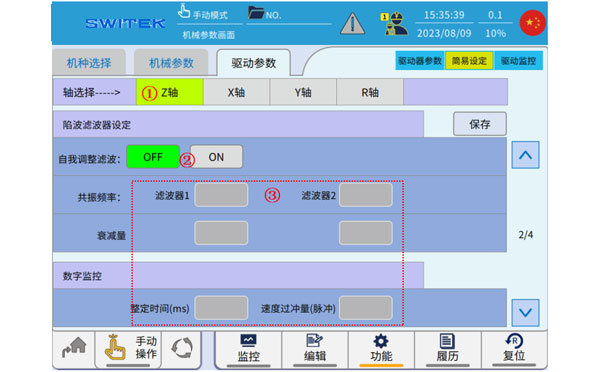
| No. | Name | Function |
|---|---|---|
| (1) | Axis selection | Click to select the axis you want to work on. |
| (2) | Adaptive filtering | Adaptive filtering function ON/OFF switching. |
| (3) | Notch filtering related parameters | Various parameters related to the notch filtering function. |
If there is a sharp sound in the servo ON at the moment or during operation, the adaptive filter can be set to ON, which will automaticall elimitate the abnormal sound caused by mechanical resonance, and can eliminate two resonance points. When the resonance frequency is set to 4000, there is no resonancde point.
Easy Setup - Vibration Control Setting
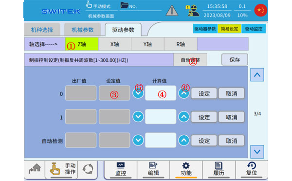
| No. | Name | Function |
|---|---|---|
| (1) | Axis selection | Select the axis you want to operate. |
| (2) | Auto-adjust | The relevant parameters of the set vibration control are automatically detected. |
| (3) | Set value | Vibration control parameters currently in use. |
| (4) | Calculated value | Calculate the derived numeric value. |
| (5) | | Apply the Calculated Value content to the Set Value. |
| (6) | | Apply the contents of the "Set Value" to the "Calculated Value". |
Vibration control setting: It is effective for suppressing vibration when stopping, and the general setting value is 5-10. The setting value can be calculated briefly based on the torque waveform, and it is difficult to set it correctly at the first time.
Easy Setup - Collision Detection
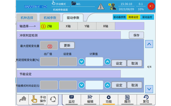
| No. | Name | Function |
|---|---|---|
| (1) | Axis Selection | The axis selection to set |
| (2) | Maximum torque variation |

SW6308D-20
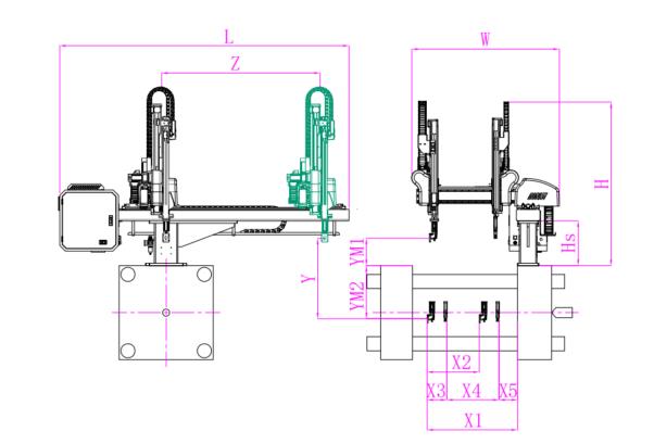
Unit: mm
| X1 | X2 | X3 | X4 | Y | YM1 | YM2 | Z | L | W | H | Payload | 740 | 640 | 140 | 415 | 800 | 235 | 565 | 1350 | 2320 | 1500 | 1460 | 3kg |
|---|
EOAT Assembly Demonstration -- Two Cavities Parts Picking EOAT with Runner Gripping
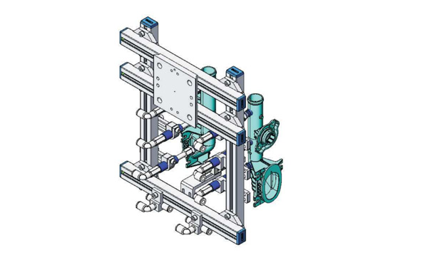
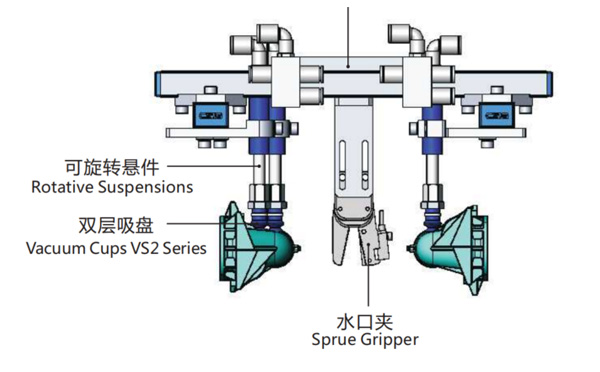
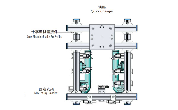
Product Descriptions
Bom List
| Product Name | PN # | Model | Quantity |
|---|---|---|---|
| Quick Changer | 7.Y00175 | QCS-G100 | 1 |
| Sprue Gripper | 8.Y00050 | GR12-12CP | 1 |
| Plugs for Profile | 4.Y00069 | PEP2518 | 10 |
| Cross Mounting Bracket for Profiles | 7.Y00194 | SMBA-2525T | 6 |
| Extruded Profile | 4.Y00455 | PEP2518-1000 | 2 |
| Vacuum Cups VS2 Series | 1.Y03085 | VS2-SA11 | 6 |
| Vacuum Cup Fitting | 7.Y00703 | VM-02-G18 | 6 |
| Rotative Suspensions | 8.Y00061 | VFR1421-G18 | 6 |
| Mounting Bracket | 7.Y00200 | SMBE1-1440T | 6 |
| Connector | 1.Y02510 | APF-M5 | 2 |
| Side Manifold Block | 7.Y00157 | SMB-06M5 | 2 |
| L-Type Threaded HOse Fitting | 1.Y02722 | APL6-01 | 8 |
| Straight Threaded Hose Fitting | 1.Y02725 | APC6-01 | 6 |
Why is SWITEK SW7112DS the Best Picking Robot for HMD368M8-SPV?
HMD368M8-SPV is the 5th generation of high speed injection molding machine by Ningbo Hwamda Machinery Co., Ltd. Which is one of the best buy injection molding machines among the producer of thin-wall containers with excellent injection speed, injection precision and competitive price. The clampling force of the HMD SPV series injection molding machine ranging from 2700Kn to 530Kn of which is the most popular injection molding machine for thin-wall containers, say 500ml cups from 4 cavities ~ 16 cavities. So, for a new thin-wall containers producer, how to choose a robot for HMD SPV series of high speed injection molding machine?
As a high speed injection molding machine, the buyers of HMD368M8-SPV mostly would be the producer of thin-wall containers of which the injection cycle time would be around 4~7s and the weight of the parts would not be much. In this case it'll request that the robot must be a high speed one. That's why we recommend SW7112DS, the high speed 3 axis injection robot by SWITEK Automation.
As a high speed 3 axis servo injection robot custom made for the thin-wall containers, the dry cycle time of SW7112DS was reduced to 3.3s only with an in minimum in mold time of 0.7s for box picking. With minor adjustment of the strokes, it's suitable for injection molding machine with clamping force from 150T ~ 550T, perfectly match the picking and stacking application of the HMD SPV series high speed injection molding machine.
For more information about SWITEK high speed robot SW7112DS please, contact Adams from SWITEK for a professional advisory about how to select a robot for your injection molding project.