
sales06@switek.biz

+86 186 5927 5869

Shopping

Subscrib to Us
sales06@switek.biz
+86 186 5927 5869
Shopping
Subscrib to Us
Keywords:IML Robot; IML Robot Operating; In Mold Labeling Robotics
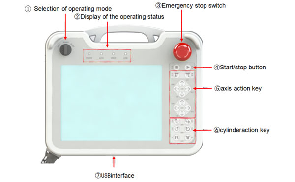
The pendant of the IML robot provide an easy to operating HMI (Human Machine Interface) for the operators of the IML robot to start the system, programming or diagnose of the IML system. Here in this chapter we'll help you to have a better understanding of the IML robot control box and the function of each part of the pantant.
Front Side:
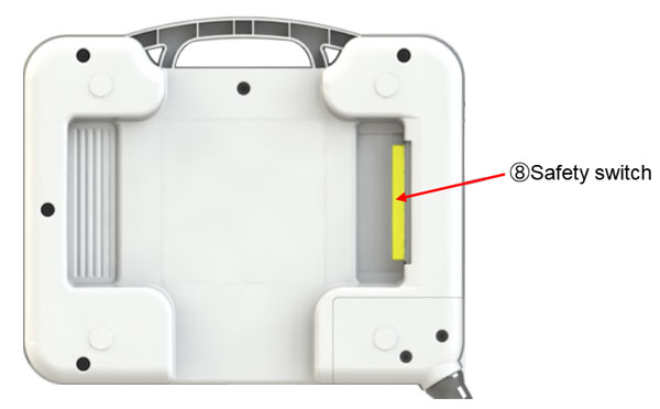
Back Side:
| No. | Name | Functions |
|---|---|---|
| 1 | Selection of operating mode | Toggle origin/manual/automatic mode |
| 2 | Display of the operating status |
|
| 3 | Emergency stop switch | Emergency stop of Take-out robot. To release the emergency stop, rotate the key along the clockwise direction. |
| 4 | Start/stop button | Start/pause operation of automatic operation. |
| 5 | Axis action key | With the safety switch, the five axes can be moved in the positive and negative directions. |
| 6 | Cylinder action key | With the safety switch, the cylinder action is controlled. |
| 7 | USB Interface | Communication interface for data upload and download on the teach pendant. |
| 8 | Safety switch | In the process of manual operation, if this key is pressed down, the actions of all manual action key can be executed. |
TSM-1000P:
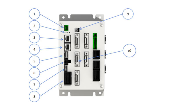
Detailed wiring description:
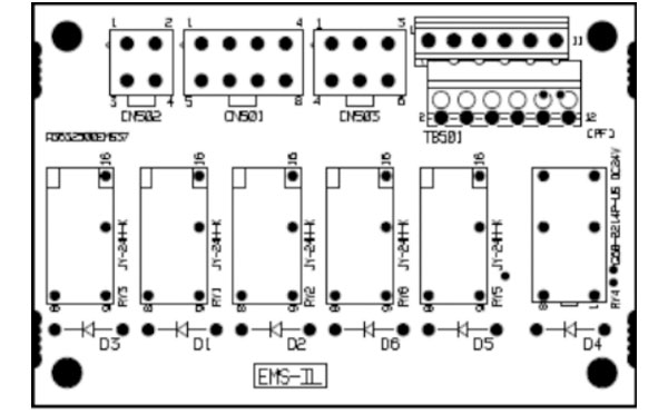
CN501:
| PIN | Label | Name | Note |
|---|---|---|---|
| 1 | X00 | M-arm up signal | Wiring to TIO-A |
| 2 | X07 | S-arm up signal | Wiring to TIO-A (short when Tri-axis) |
| 3 | X18 | Placing zone | Wiring to TIO-A |
| 4 | 24G | 24G | No wiring |
| 5 | 24G | 24G | |
| 6 | 24G | 24G | |
| 7 | 24G | 24G | |
| 8 | 24G | 24G |
CN502:
| PIN | Label | Name | Note |
|---|---|---|---|
| 1 | RY2 | Relay output (not used) | not used |
| 2 | 24V | 24V | Connect power L+ |
| 3 | 24G | 24G | |
| 4 | 24G | 24G | Connect power L- |
CN503:
| PIN | Label | Name | Note |
|---|---|---|---|
| 1 | MP_ON_1 | Servo on | Connect the I/O port on the controller (MOT) |
| 2 | EMS_1 | EMS Signal output | |
| 3 | EMS_SW_1 | EMS Signal input | |
| 4 | MP_ON_2 | Contactor servo on | |
| 5 | EMS_2 | EMS signal output | |
| 6 | EMS_SW_2 | EMS Signal input |
TB501:
| PIN | Label | Name | Note |
|---|---|---|---|
| 1 | EMS OUT1 | Take-out machine EMS output 1 | Connect cable line 23 (the line connected with the injection molding machine) |
| 2 | EMS OUT2 | Take-out machine EMS output 2 | Connect cable line 24 |
| 3 | Y35 | Enable MLD close | Connect PIN 2 in CN302 on the PIO |
| 4 | Y35 | Enable MLD close | Connect PIN6 in CN302 on the PIO |
| 5 | Y35 | Enable MLD close | Connect cable line 10 |
| 6 | Y35 | Enable MLD close | Connect cable line 11 |
| 7 | EMSIN_1(24V) | Outer EMS signal input 1 | Please connect PIN7 and PIN8 when not using the external emergency stop signal. |
| 8 | EMSIN1_1 | Outer EMS signal input 1 | |
| 9 | EMSIN1_2 | Outer EMS signal input 2 | Please connect PIN9 and PIN10 when not using the external emergency stop signal. |
| 10 | EMSIN1_2 | Outer EMS signal input 2 | |
| 11 | EMSIN1_3 | Outer EMS signal input 3 | Please connect PIN11 and PIN12 when not using the external emergency stop signal |
| 12 | EMSIN1_3 (24G) | Outer EMS signal input 3 |
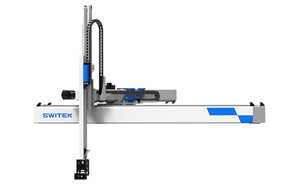
SW7730DS
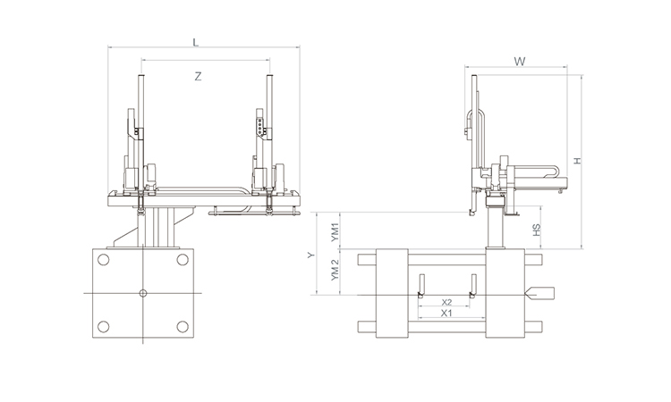
Unit: mm
| X1 | X2 | X3 | X4 | Y | YM1 | YM2 | Z | L | W | H | Payload | 2250 | 1720 | 0 | 0 | 3000 | 780 | 2220 | 4000 | 5050 | 3005 | 3440 | 75kg |
|---|
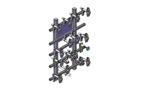
EOAT Assembly Demonstration -- Two Cavities Non-woven Fabric In Mold Insertion
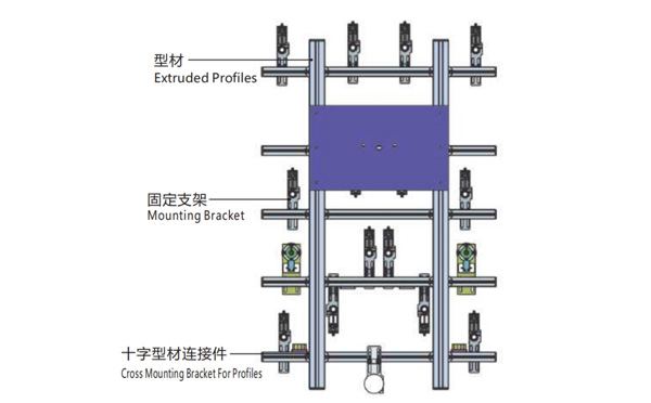
Product Descriptions
Bom List
| Product Name | PN # | Model | Quantity |
|---|---|---|---|
| Extruded Profiles | 4.Y00052 | PEP4040-1000 | 2 |
| Plugs for Profile | 4.Y00072 | PEP4040 | 4 |
| Extruded Profiles | 4.Y000481 | PEP2525-1500 | 2 |
| Extruded Profiles | 4.Y00481 | PEP2525-1000 | 1 |
| Plugs for Profile | 4.Y00070 | PEP2525 | 10 |
| Cross Mounting Bracket for Profiles | 7.Y00356-T | SMBA-2540T | 10 |
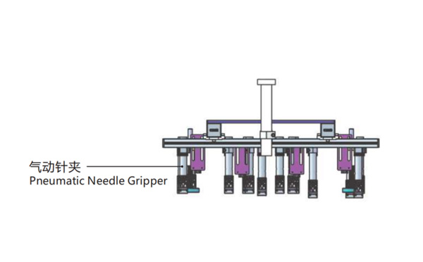
| Pneumatic Needle Gripper | 8.Y00025 | GN2010 | 14 |
| Mounting Bracket | 7.Y00308-T | SMBE2-2060T | 14 |
| Mounting Bracket | 7.Y00309-T | SMBE2-3060T | 1 |
For 20/33L Pails IML Prodcution, Which Injection Molding Machine Would Be the Best One for This IML Project?
For the IML production of 20/33L pails, HaiDa machinery, which was founded in 1992, has a special high precision injection molding machine HD700U specialized for the IML production of 20/33L IML pails. With a clamping force of 700T and enlarged opening stroke up to 1060mm, which enable it to IML produce a deeper pails.
As a mate to Haida HD700U, the largest IML Robot among the SW8 Series of SWITEK Automation SW850 provide a perfect side entry IML solutions for the IML production of 20/33L pails. The combination of Haida HD700U + SWITEK SW850 IML Robot will provide the IML pails producer a price smart pails IML Solutions.


