
sales06@switek.biz

+86 186 5927 5869

Shopping

Subscrib to Us
sales06@switek.biz
+86 186 5927 5869
Shopping
Subscrib to Us
Keywords:IML Robot; IML Robot Operating; In Mold Labeling Robotics
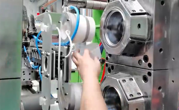
The "LEVEL" of the the IML robot against the injection molding machine and the mold are very important to the parts quality. Here we'll introduce how to install a SWITEK IML robot step by step with the "LEVEL" of the IML robot well adjusted to ensure an efficient production of high quality IML containers.
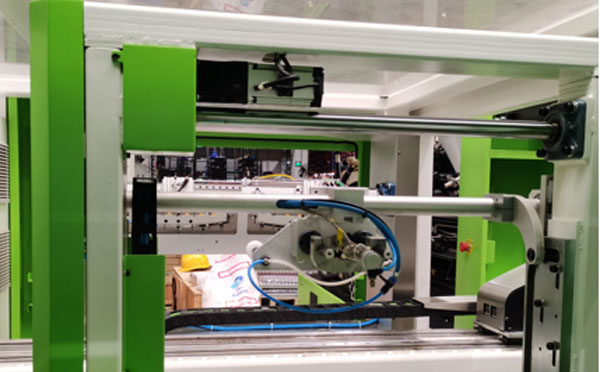
Step 1: The Layout of the IML System Installation
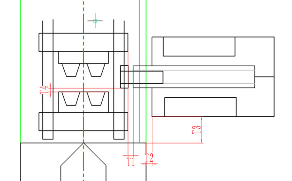
The side entry IML robot are installed to the non-operator side of the injection molding machine. The safe door to the non-operator side of the injection molding machine would be opened permanently to allow the IML robot enter the injection molding machine for parts picking and label inserting but without interfere the mold opening and close. The parameters T1, T2, T3, T4 are the general guideline of space between the IML robot to the injection molding machine and the mold in an IML system installation. Please ensure that T1 >6cm and T4 >2cm.
The T2 is the distance from the IML robot to the injection molding machine. If we're not sure what's the distance between the IML robot and the injection molding machine can be guarangeed, we must ensure that T1 >6cm to prevent the interference in production.
The distance T3 will determine the position of the IML robot arm in working to prevent the fixture from colliding with the mold while there's a minor deviation. If you're not sure what would be T3, just make sure that T4 >2cm after the fixture is installed.
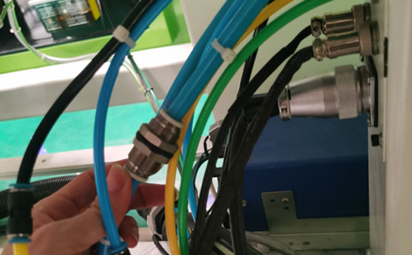
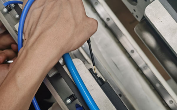
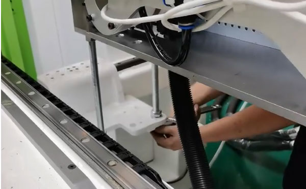
Step 2: Pipeline Connection
Connect the power supply, controller, air sosurce and start the IML robot.
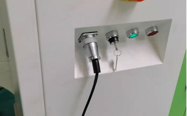
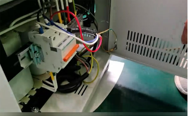
After power on, check the fixture of the IML robot and release it, manual test the movement of each axis and the action of the fixture.
You can move to the next step of IML robot starting after ensure that all the air pipes are well connected and the movements of all axis and fixtures are working well.
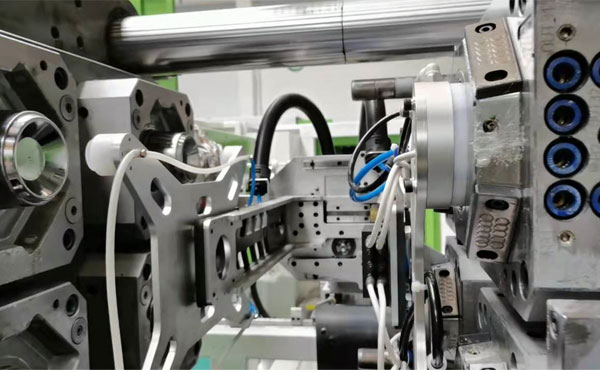
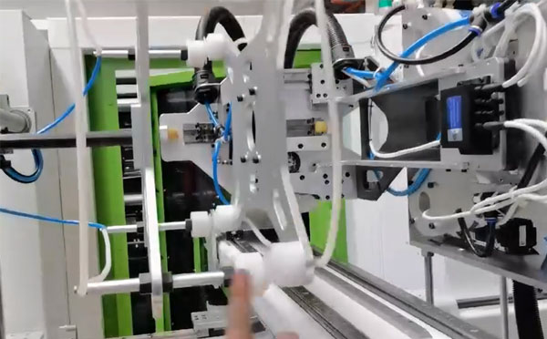
Step 3: IML Robot Start Up and Level Adjustment
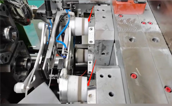
The gap between the mandrel and the mold cavity is the key to whether the robot can place the label perfectly, which will determine the quality of the IML container produced.
In a perfectly installed IML system, the IML robot dummy and the mold cavity would be on the same central axis. In this case we'll ensure that the dummy won't have any resistance when entering and exit the mold cavities and the labels would be placed without collision with uniformed position.
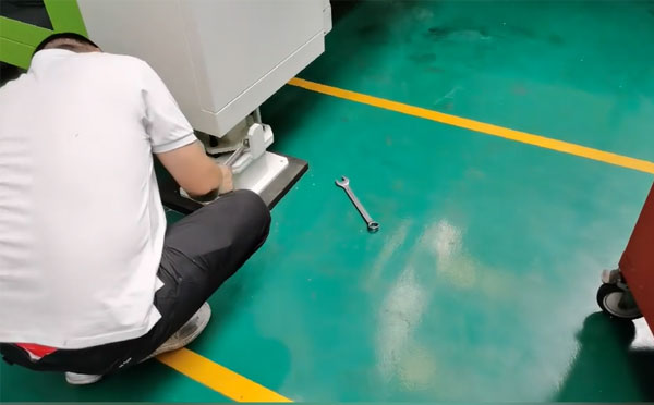
The position of the mandrel and the level of it against the mold cavity can be adjusted by the four supporting feets of the IML robot and the caps of the injection molding machine.
The procedure to adjust the level of the IML system would be:
Adjust the level of the injection molding machine → have the edge of the moving platen as the benchmark, ensure that both side of the mold are paralleled to the edge of the fixed platen.
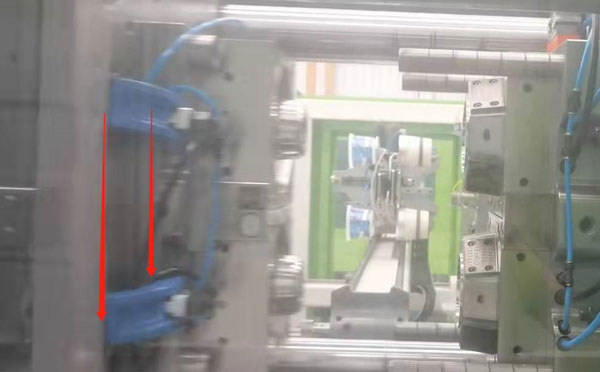
Adjust the vertical position of the IML robot against the injection molding machine. We can use a crane or a forklift to move the end of the IML robot to adjust the gap between the dummy and the mold cavity and ensure that the deviation on both side is <1mm.
By raising or lowering the column on one side of the IML robot, the upper and lower deviation of the mandrel can be corrected.
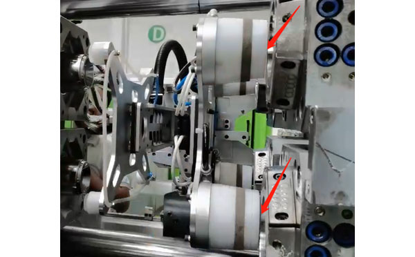
With the servo disconnected, if the mandrels can be pushed into the mold cavities manually, it means that the level of the IML robot is well adjusted.
Have one sample injected by the same mold and have the top and bottom of it cut and insert the ring of it into the mold cavity, push the mandrels into the ring and then fix the mandrel to the fixture.
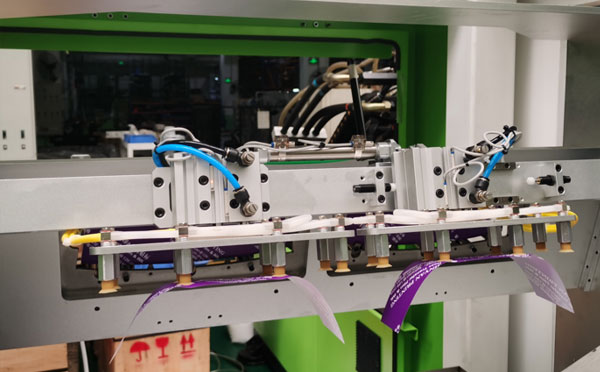
Step 4: Replacement of the Magazine and Level Adjustment.
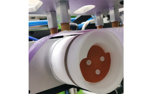
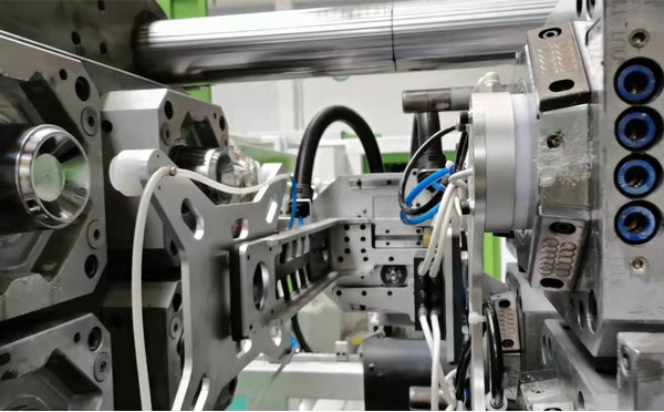
When starting up the IML robot, we can have the label picking cylinder pick one label up from the magazine and wrap it on the mandrel and keep a 1~2mm gap between the edge of the label and the bottom of the mandrel to ensured that the labels would be perfectly put into the mold cavities.
Adjust the position of the suction cup to ensure that the products can be sucked.
With all the level adjustment, the IML robot is now ready to be programed for IML containers production. Please follow the TEACHING instruction of the IML robot to modify the position where the label to be picked and placed. If you still have any question in SWITEK IML robot installation and adjustment, please feel free to contact our engineer, our online technical suppoort will always available for you.
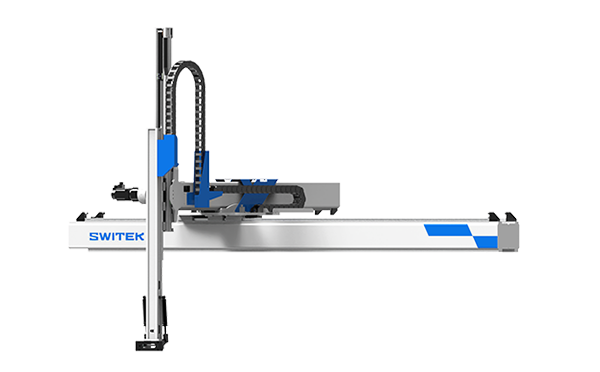
SW7312DS
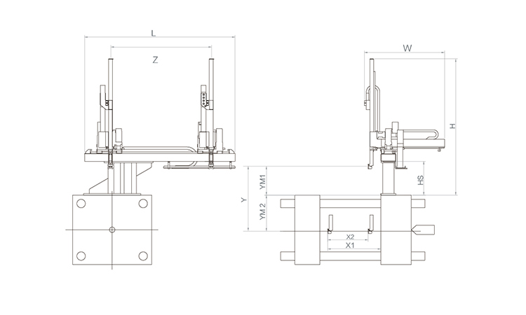
Unit: mm
| X1 | X2 | X3 | X4 | Y | YM1 | YM2 | Z | L | W | H | Payload | 1020 | 730 | 0 | 0 | 1200 | 450 | 750 | 1700 | 2600 | 1660 | 2110 | 5kg |
|---|
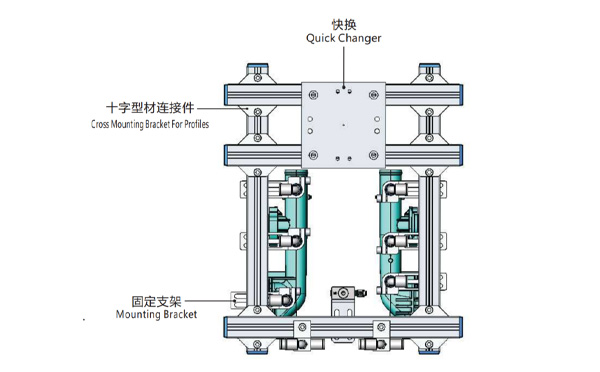
EOAT Assembly Demonstration -- Two Cavities Parts Picking EOAT with Runner Gripping
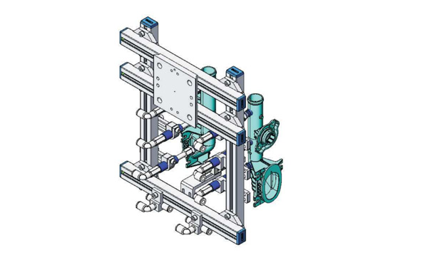
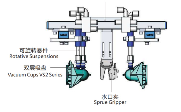
Product Descriptions
Bom List
| Product Name | PN # | Model | Quantity |
|---|---|---|---|
| Quick Changer | 7.Y00175 | QCS-G100 | 1 |
| Sprue Gripper | 8.Y00050 | GR12-12CP | 1 |
| Plugs for Profile | 4.Y00069 | PEP2518 | 10 |
| Cross Mounting Bracket for Profiles | 7.Y00194 | SMBA-2525T | 6 |
| Extruded Profile | 4.Y00455 | PEP2518-1000 | 2 |
| Vacuum Cups VS2 Series | 1.Y03085 | VS2-SA11 | 6 |
| Vacuum Cup Fitting | 7.Y00703 | VM-02-G18 | 6 |
| Rotative Suspensions | 8.Y00061 | VFR1421-G18 | 6 |
| Mounting Bracket | 7.Y00200 | SMBE1-1440T | 6 |
| Connector | 1.Y02510 | APF-M5 | 2 |
| Side Manifold Block | 7.Y00157 | SMB-06M5 | 2 |
| L-Type Threaded HOse Fitting | 1.Y02722 | APL6-01 | 8 |
| Straight Threaded Hose Fitting | 1.Y02725 | APC6-01 | 6 |
For a Container with a Height of 100mm, What Would be the Minimal Opening Stroke of the Injection Molding Machine?
As we know, for the IML production of a container, the robot will do the actions of parts picking and label inserting in the mold, which means that the system will request a much larger in mold space compared to non-IML production. While selecting an injection molding machine for your IML project, the opening stroke of the injection molding machine would be a very important parameter to be taken into consideration. The basic formular for the opening stoke caculation would be heigh of the parts x 3 + 150mm, the potential injection molding machine must have a larger opening stroke, or the robot may not able to pick the parts and insert the labels symtaneously.


