sales06@switek.biz

+86 186 5927 5869

Shopping

Subscrib to Us
sales06@switek.biz
+86 186 5927 5869
Shopping
Subscrib to Us
Keywords:Panasonic A6 Servo Installation Instruction, Panasonic A6 Driver, Panasonic A6 Series Servo Motor Manual
The correct setup of the parameter and mode of the Panasonic A6 series of servo will ensure the proper working of the Panasonic A6 series of motor and the stability of your machineries and automation system.
| Parameter No. | Title | Range | Default | Unit | Turning on of power supply | Related Control Mode | Detail page | ||||||
|---|---|---|---|---|---|---|---|---|---|---|---|---|---|
| Class | No. | A, B-frame | C-frame | D, E, F-frame | P | S | T | F | |||||
| 1 | 00 | 1st gain of position loop | 0 to 30000 | 480 | 320 | 0.1/s* | ○ | ○ | 4-16 | ||||
| 1 | 01 | 1st gain of velocity loop | 1 to 32767 | 270 | 180 | 0.1 Hz* | ○ | ○ | ○ | ○ | |||
| 1 | 02 | 1st time constant of velocity loop integration | 1 to 10000 | 210 | 310 | 0.1 ms* | ○ | ○ | ○ | ○ | |||
Caution → The symbol "*" attached to "Unit". indicates that the digits of setting unit will change if the parameter is set by using the setup support software PANATERM.
Note → Parameter describes of this page is P.4-6 to P.4-16.
| Parameter No. | Title | Range | Default | Unit | Turning on of power supply | Related Control Mode | Detail page | ||||||
|---|---|---|---|---|---|---|---|---|---|---|---|---|---|
| Class | No. | A, B-frame | C-frame | D,E,F-frame | P | S | T | F | |||||
| 1 | 03 | 1st filter of speed detection | 0 to 5 | 0 | — | ○ | ○ | ○ | ○ | 4-16 | |||
| 1 | 04 | 1st time constant of torque filter | 0 to 2500 | 84 | 126 | 0.01 ms | ○ | ○ | ○ | ○ | |||
| 1 | 05 | 2nd gain of position loop | 0 to 30000 | 480 | 320 | 0.1/s* | ○ | ○ | 4-17 | ||||
| 1 | 06 | 2nd gain of velocity loop | 1 to 32767 | 270 | 180 | 0.1Hz* | ○ | ○ | ○ | ○ | |||
| 1 | 07 | 2nd time constant of velocity loop integration | 1 to 10000 | 210 | 310 | 0.1ms* | ○ | ○ | ○ | ○ | |||
| 1 | 08 | 2nd filter of speed detection | 0 to 5 | 0 | — | ○ | ○ | ○ | ○ | ||||
| 1 | 09 | 2nd time constant of torque filter | 0 to 2500 | 84 | 126 | 0.01ms* | ○ | ○ | ○ | ○ | |||
| 1 | 10 | Velocity feed forward gain | 0 to 4000 | 1000 | 0.10 %* | ○ | ○ | ||||||
| 1 | 11 | Velocity feed forward filter | 0 to 6400 | 0 | 0.01 ms* | ○ | ○ | ||||||
| 1 | 12 | Torque feed forward gain | 0 to 2000 | 1000 | 0.10%* | ○ | ○ | ○ | 4-18 | ||||
| 1 | 13 | Torque feed forward filter | 0 to 6400 | 0 | 0.01ms* | ○ | ○ | ○ | |||||
| 1 | 14 | 2nd gain setup | 0 to 1 | 1 | — | ○ | ○ | ○ | ○ | ||||
| 1 | 15 | Mode of position control switching | 0 to 10 | 0 | — | ○ | ○ | 4-19 | |||||
| 1 | 16 | Delay time of position control switching | 0 to 10000 | 10 | 0.1ems* | ○ | ○ | ||||||
| 1 | 17 | Level of position control switching | 0 to 20000 | 0 | — | ○ | ○ | 4-20 | |||||
| 1 | 18 | Hysteresis at position control switching | 0 to 20000 | 0 | — | ○ | ○ | ||||||
| 1 | 19 | Position gain switching time | 0 to 10000 | 10 | 0.1ms* | ○ | ○ | ||||||
| 1 | 20 | Mode of velocity control switching | 0 to 5 | 0 | — | ○ | 4-21 | ||||||
| 1 | 21 | Delay time of velocity control switching | 0 to 10000 | 0 | 0.1ms* | ○ | |||||||
| 1 | 22 | Level of velocity control switching | 0 to 20000 | 0 | — | ○ | |||||||
| 1 | 23 | Hysteresis at velocity control switching | 0 to 20000 | 0 | — | ○ | 4-22 | ||||||
| 1 | 24 | Mode of torque control switching | 0 to 3 | 0 | — | ○ | |||||||
| 1 | 25 | Delay time of torque control switching | 0 to 10000 | 0 | 0.1ms* | ○ | |||||||
| 1 | 26 | Level of torque control switching | 0 to 20000 | 0 | — | ○ | |||||||
| 1 | 27 | Hysteresis at torque control switching | 0 to 20000 | 0 | — | ○ | |||||||
| 1 | 28 | For manufacturer's use | — | 1000 | — | ||||||||
| 1 | 29 | For manufacturer's use | — | 1000 | — | ||||||||
| 1 | 30 | For manufacturer's use | — | 0 | — | ||||||||
| 1 | 31 | For manufacturer's use | — | 480 | 320 | — | |||||||
| 1 | 32 | For manufacturer's use | — | 270 | 180 | — | |||||||
| 1 | 33 | For manufacturer's use | — | 210 | 310 | — | |||||||
| 1 | 34 | For manufacturer's use | — | 84 | 126 | — | |||||||
| 1 | 35 | For manufacturer's use | — | 250 | — | ||||||||
| 1 | 36 | For manufacturer's use | — | 1000 | — | ||||||||
| 1 | 37 | For Manufacturer's use | — | 1000 | — | ||||||||
| 1 | 38 | For manufacturer's use | — | 0 | — | ||||||||
| 1 | 39 | For manufacturer's use | — | 480 | 320 | — | |||||||
| 1 | 40 | For manufacturer's use | — | 270 | 180 | — | |||||||
| 1 | 41 | For manufacturer's use | — | 210 | 310 | — | |||||||
| 1 | 42 | For manufacturer's use | — | 84 | 126 | ||||||||
| 1 | 43 | For manufacturer's use | — | 250 | — | ||||||||
| 1 | 44 | For manufacturer's use | — | 1000 | — | ||||||||
| 1 | 45 | For manufacturer's use | — | 1000 | — | ||||||||
| 1 | 46 | For manufacturer's use | — | 0 | — | ||||||||
| 1 | 47 | For manufacturer's use | — | 480 | 320 | 320 | |||||||
| 1 | 48 | For manufacturer's use | — | 270 | 180 | — | |||||||
| 1 | 49 | For manufacturer's use | — | 210 | 310 | — | |||||||
| 1 | 50 | For manufacturer's use | — | 84 | 126 | — | |||||||
| 1 | 51 | For manufacturer's use | — | 250 | — | ||||||||
| 1 | 52 | For manufacturer's use | — | 1000 | — | ||||||||
| 1 | 53 | For manufacturer's use | — | 1000 | — | ||||||||
| 1 | 54 | For manufacturer's use | — | 0 | — | ||||||||
| 1 | 55 | For manufacturer's use | — | 480 | 320 | — | |||||||
| 1 | 56 | For manufacturer's use | — | 270 | 180 | — | |||||||
| 1 | 57 | For manufacturer's use | — | 210 | 310 | — | |||||||
| 1 | 58 | For manufacturer's use | — | 84 | 126 | — | |||||||
| 1 | 59 | For manufacturer's use | — | 250 | — | ||||||||
| 1 | 60 | For manufacturer's use | — | 1000 | — | ||||||||
| 1 | 61 | For manufacturer's use | — | 1000 | — | ||||||||
| 1 | 62 | For manufacturer's use | — | 0 | — | ||||||||
| 1 | 63 | For manufacturer's use | — | 480 | 320 | — | |||||||
| 1 | 64 | For manufacturer's use | — | 270 | 180 | — | |||||||
| 1 | 65 | For manufacturer's use | — | 210 | 310 | — | |||||||
| 1 | 66 | For manufacturer's use | — | 84 | 126 | — | |||||||
| 1 | 67 | For manufacturer's use | — | 250 | — | ||||||||
| 1 | 68 | For manufacturer's use | — | 1000 | — | ||||||||
| 1 | 69 | For manufacturer's use | — | 1000 | — | ||||||||
| 1 | 70 | For manufacturer's use | — | 0 | — | ||||||||
| 1 | 71 | For manufacturer's use | — | 480 | 320 | — | |||||||
| 1 | 72 | For manufacturer's use | — | 270 | 180 | — | |||||||
| 1 | 73 | For manufacturer's use | — | 210 | 310 | — | |||||||
| 1 | 74 | For manufacturer's use | — | 84 | 126 | — | |||||||
| 1 | 75 | For manufacturer's use | — | 250 | — | ||||||||
| 1 | 76 | For manufacturer's use | — | 1000 | — | ||||||||
| 1 | 77 | For manufacturer's use | — | 1000 | — | ||||||||
| 1 | 78 | For manufacturer's use | — | 0 | — | ||||||||

SW6712D-20
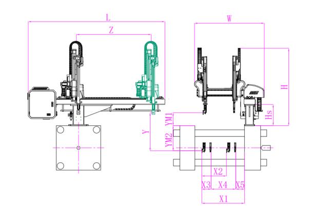
Unit: mm
| X1 | X2 | X3 | X4 | Y | YM1 | YM2 | Z | L | W | H | Payload | 1025 | 605 | 250 | 590 | 1200 | 475 | 725 | 2000 | 3020 | 1610 | 2050 | 8kg |
|---|
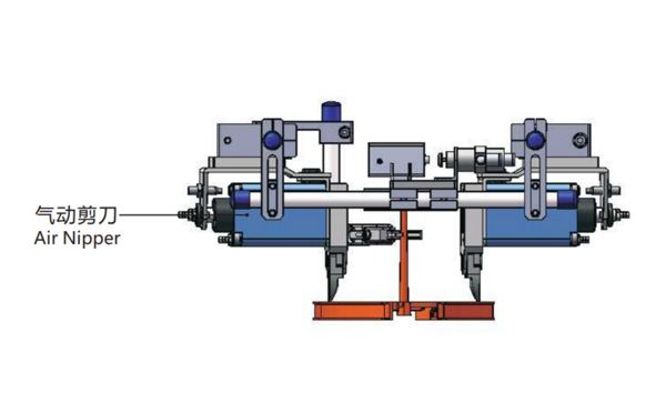
EOAT Assembly Demonstration -- Two Cavities Parts Picking EOAT with Runner Cutting by Air Nipper
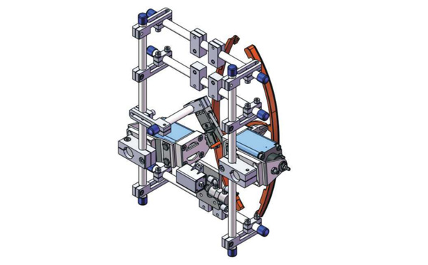
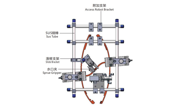
Product Descriptions
Bom List
| Product Name | PN # | Model | Quantity |
|---|---|---|---|
| Sus Tube | 4.Y00021 | PST12-1500 | 2 |
| Air Nipper | 1.Y00004 | GT-NY25 | 2 |
| Straight Blades for Plastic | 1.Y00037 | NY25AJ | 2 |
| Fixing Block | 7.Y00633 | SCE2-25 | 2 |
| Tube Plugs | 1.Y03638 | PST12-1500 | 11 |
| Cross Connector | 7.Y00027 | SMBT-2012 | 2 |
| Access Robot Bracket | 7.Y00002 | SMBH1-12M6 | 6 |
| L-Type Thread Hose Fitting | 1.Y02809 | APL6-M5 | 3 |
| Slide Bracket | 7.Y00004 | SCF4-1240W16 | 7 |
| Slide Bracket | 7.Y00001 | SMBS-12T16 | 7 |
| Sprue Gripper | 8.Y00091 | GR12-12-CN | 1 |
| Cross Connector | 7.Y00020 | SMBT-1212 | 1 |
What's the Working Process of SWITEK Ball Valve Injection Automation System?
PVC/PPR ball valve is a very important pipe fittings in the drainage system in control of the water flow. But the injection production of a ball valve it'll need to insert the core of the valve with the sealing ring into the mold. The in mold insertion of the spare parts would be done manually which the cost is increasing with the getting higher labour cost and difficult to increase the productivity. That's why LESSO group invited SWITEK Automation to develop a series of pipe fittings auto-production solutions, among which include the Ball Valve Core Insertion System.
Designated to design an economic but efficient automation solution of ball valve injection production, the SWITEK 4 cavities ball valve in mold insertion solutions include the following functions:
For detailed cofiguration of SWITEK ball valve injection automation system please contact Adams of SWITEK to get a turn-key automation solutions of PVC/PPR ball valve production.