SWITEK IML Robot Instruction -- SigmaTek -- Function Screen
Abstract
With the control system developed by the Austria automatic company SIGMATEK GmbH & Co KG, SWITEK high speed side entry IML robot is providing a more efficient and outstanding performance for your quality bulk production of the IML Yogurt Cups.
1.3 Function Screen
1.3.1 Function Screen
Click Function button into function screen, as the picture below 1.3.1;
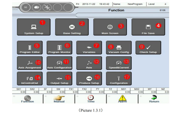
Set some system function parameters;
Set language, unit, date, screen saver, change Password and parameter auto save period;
Main screen;
Use for Program/servo parameter/IO parameter/system parameter/system even save etc;
Program Editor;
Program Monitor;
Use for variables parameter settings, variable naming operations etc;
Vacuum config;
Check whether relevant feedback signals and other function signals use;
Used to set the usage of each axis, Including servo axis andd pneumatic axis And set reference sequence, reference point etc;
Used to set sevo running speed, each axis gain parameters and servo alarm message, clear servo alarm etc;
For each axis running parameters Settings;
Used to monitor the real-time speed, current value and torque of each axis;
Use the input signal to control the output signal;
At the automatic runtime out whether disconnect the corresponding output;
Set the parameters related to production;
Set including Select type of the machine, the status of Module configuration and Module check etc;
1.3.2 System Setup Screen
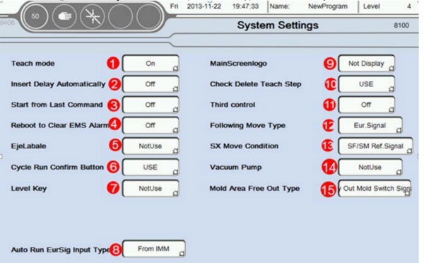
When Axis set position, direct input end position if the mode is Program Editor; When Axis set position, need to manually move the axis to be desired position if the mode is Program Editor;
Need to manually add the delay orders after insert action if the mode is Program Editor;
System will automatically add delay command after insert action if the mode is Program Editor;
Machine stop after occur error when automatic. When start automatically again, the machine continue to run follow the steps to stop before;
Machine stop after error when automatic. When start automatically again, the machine continue to run follow the first step form program;
After reboot emergency switch, need to restart clear the emergency alarm. After reboot emergency switch, emergency alarm clear;
Do not use EjeLabel; Use EjeLabel;
Cycle run confirm button, Click three buttons of the Controller on the left from top to bottom successively, beginning to run automatically; Cycle run use confirm button, needed peripheral switch signal to trigger the cycle run after click three buttons of the controller on the left from top to bottom successively. This function is applicable to the safety confirmation before cycle run;
Do not use level key (Need higher lever authority); Use level key (Need higher level authority);
Needs to access Open/Close mould, robot automatic etc When cycle run from injection moulding machine. Can be cycle run do not need to obtain relevant signals from the injection molding machine.
Display manufacture LOGO on main screen; Do not display manufacturer LOGO on main screen.
Confirm delete message appears when delete program step if the mode is program editor;
Direct delete program step and message do not appear when delete program step if the mode is program editor, In order to prevent the program steps accidentally deletedd, Suggest to open this function;
If click light upleft first button of controller when robot ar used, Output 24V to injection molding machine, else output 0V.
If click light upleft first button of controller when robot are used. Output 0V to injection molding machine, else output 24V.
The part of the operation can be controlled by the injection molding machine manipulator. Limited to (Enable, startup, stop, Passwrod level change, speed change etc. );
Robot can to enter after receives the mould complete; Robot can to enter afte corresponding grating signal was detected; Robot can to enter after open mold to set position (robot follow-up); Robot can to enter after open mold to set position and corresponding grating signal was detected; (robot follow-up);
Best Buy Robotic Arm for Injection Molding Machine
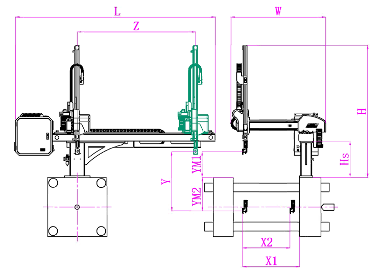
SW6712S
Unit: mm
X1
X2
X3
X4
Y
YM1
YM2
Z
L
W
H
Payload
900
840
0
0
1200
420
780
2000
3020
1610
2050
8kg
The Application of End of Robotic Arm Tooling
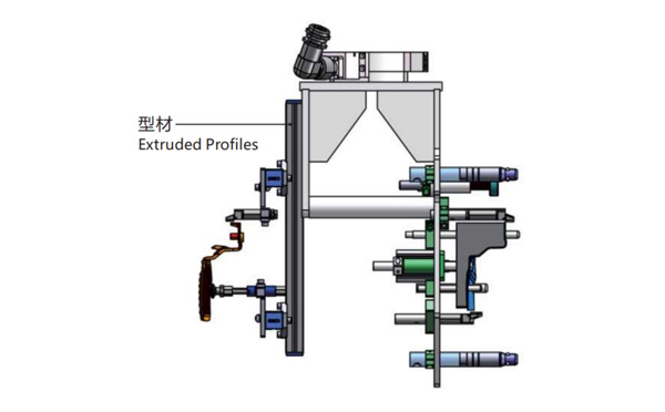
EOAT Assembly Demonstration -- One Cavity In Mold Insertion EOAT With Mold Positioner
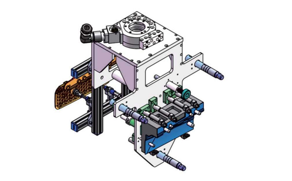
One Cavity In Mold Insertion EOAT With Mold Positioner
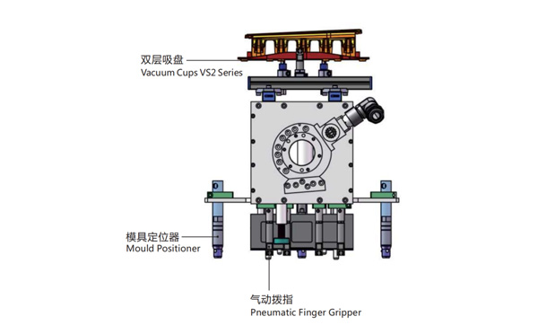
Product Descriptions
This EOAT is for One Cavity Parts Picking and In Mold Insertion;
The EOAT has Two Sides, One Side for Parts Picking, the Oter Side for In Mold Insertion;
The Parts Would be Picked by the Vacuum Cups and One Finger Angular Pneumatic Gripper;
The EOAT to be Drived by Three Air Circuits, One for the Cylinder, the Other for Finger Angular Pneumatic Gripper and the Third One for Mould Positioner;
The Gross Weight of the EOAT Seet is about 9kg.
Bom List
Product Name
PN #
Model
Quantity
Extruded Profiles
4.Y00481
PEP2525-1500
1
Plugs for Profile
4.Y00070
PEP2525
8
Mould Positioner
8.Y00088
GMP20A
3
Vacuum Cups VS2 Series
1.Y05310
VS2-SA20
2
Rotative Suspensions
8.Y00061
VFR1421-G18
2
Pneumatic Finger Gripper
8.Y00084
GFR14-95G
7
Extension Tube
7.Y00733
SMBY14-50
6
Mounting Bracket
7.Y00200-T
SMBE1-1440T
3
Cross Mounting Bracket for Profiles
7.Y00194-T
SMBA-2525T
4
Vacuum Cup Fittings
7.Y00703
VM02-G18
2
Q & A About Robotic Arms and Injection Automation
Why There's An Additional Static Charge Ring Installed to Some IML System?
For visitors of SWITEKK website will find that for the IML system no matter if it's side entry IML robot or Top Entry IML Robot, you can see a ring just outside the mold area in some of the IML system but not to the other IML system. Why would it happen and what's the function of this ring to the IML system?
The ring installed is a static charging ring. For a better understanding of the function of this static charging ring we'll need to know the types of the labels which we're using in an IML project. For an IML container made from PP (Polypropylene) there're two main types of IML labels, the regular material IML labels which could be easily static charged from the inner side of the label and the metallic label of which has a metallic layer will releas the static immediately. In this case we'll need to have the label static charged from outside of the label. That's why an extra static charging ring is to be installed to the IML system to ensure that the metallic IML label could be well static charged.
For more knowledge about IML and IML solutions just follow up https://www.gechiml.com for the up to date solutions of IML from SWITEK automation and contact Adams for a turn-key solutions of IML.