sales06@switek.biz

+86 186 5927 5869

Shopping

Subscrib to Us
sales06@switek.biz
+86 186 5927 5869
Shopping
Subscrib to Us
Keywords:Panasonic A6 Servo Installation Instruction, Panasonic A6 Driver, Panasonic A6 Series Servo Motor Manual
The correct setup of the parameter and mode of the Panasonic A6 series of servo will ensure the proper working of the Panasonic A6 series of motor and the stability of your machineries and automation system.
| Parameter No. | Title | Range | Default | Unit | Turning on of power supply | Related Control Mode | Detail page | ||||||
|---|---|---|---|---|---|---|---|---|---|---|---|---|---|
| Class | No. | A, B-frame | C-frame | D,E,F-frame | P | S | T | F | |||||
| 5 | 00 | 2nd numberator of electronic gear | 0 to 230 | 0 | — | ○ | ○ | 4-52 | |||||
| 5 | 01 | 3rd numberator of electronic gear | 0 to 230 | 3 | — | ○ | ○ | ||||||
| 5 | 02 | 4th numberator of electronic gear | 0 to 230 | 3 | — | ○ | ○ | ||||||
| 5 | 03 | Denominator of pulse output division | 0 to 8388608 | 0 | — | ○ | ○ | ○ | ○ | ○ | |||
| 5 | 04 | Over-travel inhibit input setup | 0 to 2 | 1 | — | ○ | ○ | ○ | ○ | ○ | |||
| 5 | 05 | Sequence at over-travel inhibit | 0 to 2 | 0 | — | ○ | ○ | ○ | ○ | ○ | 4-53 | ||
| 5 | 06 | Sequence at Servo-Off | 0 to 9 | 0 | — | ○ | ○ | ○ | ○ | 4-54 | |||
| 5 | 07 | Sequence at main power OFF | 0 to 9 | 0 | — | ○ | ○ | ○ | ○ | ||||
| 5 | 08 | LV trip selection at main power OFF | 0 to 3 | 1 | — | ○ | ○ | ○ | ○ | 4-55 | |||
| 5 | 09 | Detection time of main power off | 20 to 2000 | 70 | 1 ms | ○ | ○ | ○ | ○ | ○ | |||
| 5 | 10 | Sequence at alarm | 0 to 7 | 0 | — | ○ | ○ | ○ | ○ | ||||
| 5 | 11 | Torque setup for emergency stop | 0 to 500 | 0 | % | ○ | ○ | ○ | ○ | 4-56 | |||
| 5 | 12 | Over-load level setup | 0 to 500 | 0 | % | ○ | ○ | ○ | ○ | ||||
| 5 | 13 | Over-speed level setup | 0 to 20000 | 0 | r/min | ○ | ○ | ○ | ○ | ||||
| 5 | 14 | Motor working range setup | 0 to 1000 | 10 | 0.1 revolution* | ○ | ○ | ||||||
| 5 | 15 | I/F reading filter | 0 to 3 | 0 | — | ○ | ○ | ○ | ○ | ○ | |||
| 5 | 16 | Alarm clear input setup | 0 to 1 | 0 | — | ○ | ○ | ○ | ○ | ○ | |||
| 5 | 17 | Counter clear input mode | 0 to 4 | 3 | — | ○ | ○ | 4-57 | |||||
| 5 | 18 | Invalidation of command pulse inhibit input | 0 to 1 | 1 | — | ○ | ○ | ||||||
| 5 | 19 | Command pulse inhibit input reading setup | 0 to 5 | 0 | — | ○ | ○ | ○ | |||||
| 5 | 20 | Position setup unit select | 0 to 1 | 0 | — | ○ | ○ | ○ | 4-58 | ||||
| 5 | 21 | Selection of torque limit | 0 to 6 | 1 | — | ○ | ○ | ○ | |||||
| 5 | 22 | 2nd torque limit | 0 to 500 | 500*1 | % | ○ | ○ | ○ | |||||
| 5 | 23 | Torque limit switching setup 1 | 0 to 4000 | 0 | ms/100% | ○ | ○ | ○ | |||||
| 5 | 24 | Torque limit switching setup 2 | 0 to 4000 | 0 | ms/100% | ○ | ○ | ○ | 4-59 | ||||
| 5 | 25 | External input positive direction torque limit | 0 to 500 | 500*1 | % | ○ | ○ | ○ | |||||
| 5 | 26 | External input negative direction torque limit | 0 to 500 | 500*1 | % | ○ | ○ | ○ | |||||
| 5 | 27 | Input gain of analog torque limit | 10 to 100 | 30 | 0.1V/100%* | ○ | ○ | ○ | |||||
| 5 | 28 | LED initial status | 0 to 42 | 1 | — | ○ | ○ | ○ | ○ | ○ | 4-60 | ||
| 5 | 29 | RS232 baud rate setup | 0 to 7 | 2 | — | ○ | ○ | ○ | ○ | ○ | |||
| 5 | 30 | RS485 baud rate setup | 0 to 7 | 2 | — | ○ | ○ | ○ | ○ | ○ | |||
| 5 | 31 | Axis address | 0 to 127 | 1 | — | ○ | ○ | ○ | ○ | ○ | 4-61 | ||
| 5 | 32 | Command pulse input maximum setup | 250 to 8000 | 4000 | kpulse/s | ○ | ○ | ○ | |||||
| 5 | 33 | Pulse regenerative output limit setup | 0 to 1 | 0 | — | ○ | ○ | ○ | ○ | ○ | |||
| 5 | 34 | For manufacturer's use | — | 4 | — | ||||||||
| 5 | 35 | Front panel lock setup | 0 to 1 | 0 | — | ○ | ○ | ○ | ○ | ○ | |||
| 5 | 36 | For manufacturer's use | — | 0 | — | 4-62 | |||||||
| 5 | 37 | Modbus connection setting | 0 to 2 | 0 | — | ○ | ○ | ○ | ○ | ○ | |||
| 5 | 38 | Modbus communication setting | 0 to 5 | 0 | — | ○ | ○ | ○ | ○ | ○ | |||
| 5 | 39 | Modbus response waiting time | 0 to 10000 | 0 | ms | ○ | ○ | ○ | ○ | ||||
| 5 | 40 | Modbus communication timeout time | 0 to 10000 | 0 | ms | ○ | ○ | ○ | ○ | ||||
| 5 | 41 | For manufacturer's use | — | 0 | — | ||||||||
| 5 | 42 | Modbus broadcast setting | -32768 to 32767 | 0 | — | ○ | ○ | ○ | ○ | 4-63 | |||
| 5 | 45 | Quadrant projection positive direction compensation value | -1000 to 1000 | 0 | 0.1% | ○ | ○ | ||||||
| 5 | 46 | Quadrant projection negative direction comensation value | -1000 to 1000 | 0 | % | ○ | ○ | ||||||
| 5 | 47 | Quadrant projection compensation delay time | 0 to 1000 | 0 | ms | ○ | ○ | ||||||
| 5 | 48 | Quadrant projection compensation filter setting L | 0 to 6400 | 0 | 0.01 ms | ○ | ○ | ||||||
| 5 | 49 | Quadrant projection compensation filter setting H | 0 to 10000 | 0 | 0.1 ms | ○ | ○ | ||||||
| 5 | 50 | For manufacturer's use | — | 0 | — | 4-64 | |||||||
| 5 | 51 | For manufacturer's use | — | 0 | — | ||||||||
| 5 | 52 | For manufacturer's use | — | 0 | — | ||||||||
| 5 | 53 | For manufacturer's use | — | 0 | — | ||||||||
| 5 | 54 | For manufacturer's use | — | 0 | — | ||||||||
| 5 | 55 | For manufacturer's use | — | 0 | — | ||||||||
| 5 | 56 | Slow stop deceleration time setting | 0 to 10000 | 0 | ms/(1000 r/min) | ○ | |||||||
| 5 | 57 | Slow stop S-shape acceleration and deceleration setting | 0 to 1000 | 0 | ms | ○ | |||||||
| 5 | 58 | Modbus mirror register setting 1*1 | -32768 to 32767 | 24591 | — | ○ | ○ | ○ | ○ | ○ | |||
| 5 | 59 | Modbus mirror register setting 2*1 | -32768 to 32767 | 24592 | — | ○ | ○ | ○ | ○ | ○ | |||
| 5 | 60 | Modbus mirror register setting 3*1 | -32768 to 32767 | 16421 | — | ○ | ○ | ○ | ○ | ○ | |||
| 5 | 61 | Modbus mirror register setting 4*1 | -32768 to 32767 | 24613 | — | ○ | ○ | ○ | ○ | ○ | 4-65 | ||
| 5 | 62 | Modbus mirror register setting *1 | -32768 to 32767 | 17429 | — | ○ | ○ | ○ | ○ | ○ | |||
| 5 | 63 | Modbus mirror register setting 6*1 | -32768 to 32767 | 17418 | — | ○ | ○ | ○ | ○ | ○ | |||
| 5 | 64 | Modbus mirror register setting 7*1 | -32768 to 32767 | 17427 | — | ○ | ○ | ○ | ○ | ○ | |||
| 5 | 65 | Modbus mirror register setting 8*1 | -32768 to 32767 | 17419 | — | ○ | ○ | ○ | ○ | ○ | |||
| 5 | 66 | Deterioration diagnosis convergence judgment time | 0 to 10000 | 0 | 0.1s | ○ | ○ | ○ | ○ | ○ | |||
| 5 | 67 | Deterioration diagnosis inertia ratio upper limit | 0 to 10000 | 0 | % | ○ | ○ | ○ | ○ | ○ | |||
| 5 | 68 | Deterioration diagnosis inertia ratio lower limit | 0 to 10000 | 0 | % | ○ | ○ | ○ | ○ | ○ | |||
| 5 | 69 | Deterioration diagnosis unbalanced load upper limit | -1000 to 1000 | 0 | 0.1% | ○ | ○ | ○ | ○ | ○ | |||
| 5 | 70 | Deterioration diagnosis unbalanced load lower limit | -1000 to 1000 | 0 | 0.1% | ○ | ○ | ○ | ○ | ○ | |||
| 5 | 71 | Deterioration diagnosis dynamic friction upper limit | -1000 to 1000 | 0 | 0.1% | ○ | ○ | ○ | ○ | ○ | 4-66 | ||
| 5 | 72 | Deterioration diagnosis dynamic friction lower limit | -1000 to 1000 | 0 | 0.1% | ○ | ○ | ○ | ○ | ○ | |||
| 5 | 73 | Deterioration diagnosis viscous friction upper limit | 0 to 10000 | 0 | 0.1%/(10000 r/min) | ○ | ○ | ○ | ○ | ○ | |||
| 5 | 74 | Deterioration diagnosis viscous friction lower limit | 0 to 10000 | 0 | 0.1%/(10000 r/min) | ○ | ○ | ○ | ○ | ○ | |||
| 5 | 75 | Deterioration diagnosis velocity setting | -20000 to 20000 | 0 | r/min | ○ | ○ | ○ | ○ | ○ | |||
| 5 | 76 | Deterioration diagnosis torque average time | 0 to 10000 | 0 | ms | ○ | ○ | ○ | ○ | ○ | |||
| 5 | 77 | Deterioration diagnosis torque upper limit | -1000 to 1000 | 0 | 0.1% | ○ | ○ | ○ | ○ | ○ | |||
| 5 | 78 | Deterioration diagnosis torque lower limit | -1000 to 1000 | 0 | 0.1% | ○ | ○ | ○ | ○ | ○ | |||
| 5 | 79 | Modbus mirror register setting 9*1 | -32768 to 32767 | 17410 | — | ○ | ○ | ○ | ○ | ○ | 4-67 | ||
| 5 | 80 | Modbus mirror register setting 10*1 | -32768 to 32767 | 17411 | — | ○ | ○ | ○ | ○ | ○ | |||
| 5 | 81 | Modbus mirror register setting 11*1 | -32768 to 32767 | 16398 | — | ○ | ○ | ○ | ○ | ○ | |||
| 5 | 82 | Modbus mirror register setting 12*1 | -32768 to 32767 | 16402 | — | ○ | ○ | ○ | ○ | ○ | |||
| 5 | 83 | Modbus mirror register setting 13*1 | -32768 to 32767 | 16411 | — | ○ | ○ | ○ | ○ | ○ | |||
| 5 | 84 | Modbus mirror register setting 14*1 | -32768 to 32767 | 16405 | — | ○ | ○ | ○ | ○ | ○ | |||
| 5 | 85 | Modbus mirror register setting 15*1 | -32768 to 32767 | 16406 | — | ○ | ○ | ○ | ○ | ○ | |||
| 5 | 86 | Modbus mirror register setting 16*1 | -32768 to 32767 | 0 | — | ○ | ○ | ○ | ○ | ○ | |||
SW7312DS
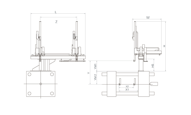
Unit: mm
| X1 | X2 | X3 | X4 | Y | YM1 | YM2 | Z | L | W | H | Payload | 1020 | 730 | 0 | 0 | 1200 | 450 | 750 | 1700 | 2600 | 1660 | 2110 | 5kg |
|---|
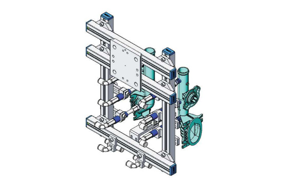
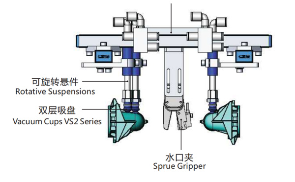
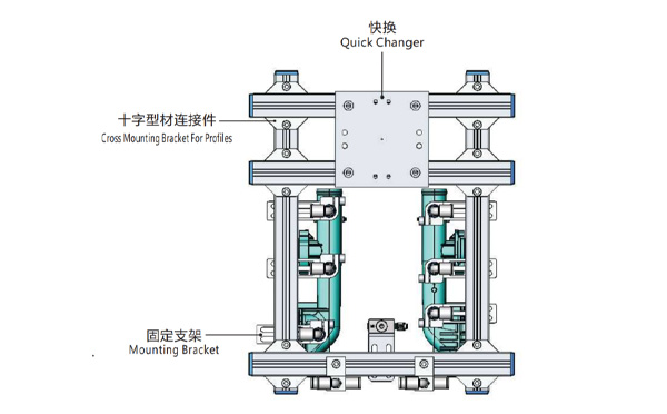
EOAT Assembly Demonstration -- Two Cavities Parts Picking EOAT with Runner Gripping
Product Descriptions
Bom List
| Product Name | PN # | Model | Quantity |
|---|---|---|---|
| Quick Changer | 7.Y00175 | QCS-G100 | 1 |
| Sprue Gripper | 8.Y00050 | GR12-12CP | 1 |
| Plugs for Profile | 4.Y00069 | PEP2518 | 10 |
| Cross Mounting Bracket for Profiles | 7.Y00194 | SMBA-2525T | 6 |
| Extruded Profile | 4.Y00455 | PEP2518-1000 | 2 |
| Vacuum Cups VS2 Series | 1.Y03085 | VS2-SA11 | 6 |
| Vacuum Cup Fitting | 7.Y00703 | VM-02-G18 | 6 |
| Rotative Suspensions | 8.Y00061 | VFR1421-G18 | 6 |
| Mounting Bracket | 7.Y00200 | SMBE1-1440T | 6 |
| Connector | 1.Y02510 | APF-M5 | 2 |
| Side Manifold Block | 7.Y00157 | SMB-06M5 | 2 |
| L-Type Threaded HOse Fitting | 1.Y02722 | APL6-01 | 8 |
| Straight Threaded Hose Fitting | 1.Y02725 | APC6-01 | 6 |
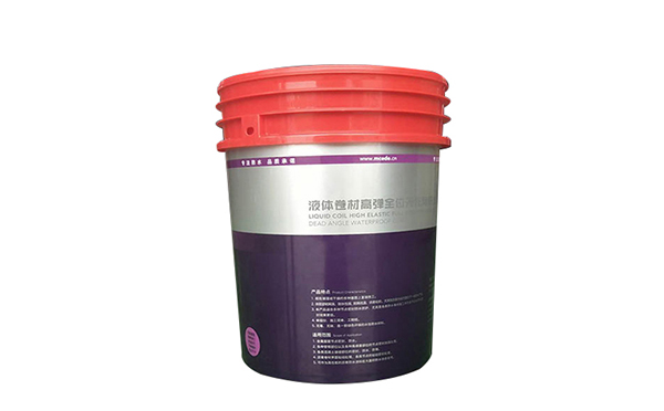
Why is BOLE BL530EKH an Ideal Injection Molding Machine for 20L IML Paints Pails Project?
BL530EKH is a hydraulic servo energy saving injection molding machine with a clamping force of 5300kN with BOLE central clamping toggle technology, which will have a higher clamping force efficiency against traditional edge clamping force and can save 2~5% material. But, the most attractive feature of this machine to an IML Paint Buckets projector is its opening stroke: 850mm.
For any IML projectors of 20L IML paint buckets the opening stroke is very important to compose an IML system economically. With an opening stroke of 850mm it means that this BL530EKH is suitable for the IML production of most paint buckets with a height < 350mm. It'll have most of the 20L paint buckets included. Compared to its counter part of which mostly would be injection molding machine > 600T, it would be a big budget saving.
Anyway before any decision made about the which injection molding machine to choose for your IML project, the right process would be to provide the sample or 3D drawing of the paint bucket of which you want to produce so SWITEK engineer will evaluate it and make a professional advisory accordingly. If you still have any question about IML paint buckets production please feel free to contact Adams from SWITEK for a budget smart solutions of IML.