sales06@switek.biz

+86 186 5927 5869

Shopping

Subscrib to Us
sales06@switek.biz
+86 186 5927 5869
Shopping
Subscrib to Us

Keywords:Panasonic A6 Servo Installation Instruction, Panasonic A6 Driver, Panasonic A6 Series Servo Motor Manual
The correct setup of the parameter and mode of the Panasonic A6 series of servo will ensure the proper working of the Panasonic A6 series of motor and the stability of your machineries and automation system.
| Parameter No. | Title | Range | Deafault | Unit | Tuming on of power supply | Related Control Mode | Detail page | ||||||
|---|---|---|---|---|---|---|---|---|---|---|---|---|---|
| Class | No. | A,B-frame | C-frame | D,E,F-frame | P | S | T | F | |||||
| 2 | 00 | Adaptive filter mode setup | 0 to 6 | 0 | — | ○ | ○ | ○ | 4-23 | ||||
| 2 | 01 | 1st notch frequency | 50 to 5000 | 5000 | Hz | ○ | ○ | ○ | ○ | ||||
| 2 | 02 | 1st notch width selection | 0 to 20 | 2 | — | ○ | ○ | ○ | ○ | ||||
| 2 | 03 | 1stnotch depth selection | 0 to 99 | 0 | — | ○ | ○ | ○ | ○ | ||||
| 2 | 04 | 2nd notch width frequency | 50 to 5000 | 5000 | Hz | ○ | ○ | ○ | ○ | ||||
| 2 | 05 | 2nd notch width selection | 0 to 20 | 2 | — | ○ | ○ | ○ | ○ | 4-24 | |||
| 2 | 06 | 2nd notch deptch selection | 0 to 99 | 0 | — | ○ | ○ | ○ | ○ | ||||
| 2 | 07 | 3rd notch frequency | 50 to 5000 | 5000 | Hz | ○ | ○ | ○ | ○ | ||||
| 2 | 08 | 3rd notch width selection | 0 to 20 | 2 | — | ○ | ○ | ○ | ○ | ||||
| 2 | 09 | 3rd notch depth selection | 0 to 99 | 0 | — | ○ | ○ | ○ | ○ | ||||
| 2 | 10 | 4th notch frequency | 50 to 5000 | 5000 | Hz | ○ | ○ | ○ | ○ | ||||
| 2 | 11 | 4th notch width selection | 0 to 20 | 2 | — | ○ | ○ | ○ | ○ | ||||
| 2 | 12 | 4th notch depth selection | 0 to 99 | 0 | — | ○ | ○ | ○ | ○ | 4-25 | |||
| 2 | 13 | Selection of damping filter switching | 0 to 6 | 0 | — | ○ | ○ | ||||||
| 2 | 14 | 1st damping frequency | 0 to 3000 | 0 | 0.1Hz* | ○ | ○ | 4-26 | |||||
| 2 | 15 | 1st damping filter setup | 0 to 1500 | 0 | 0.1Hz* | ○ | ○ | ||||||
| 2 | 16 | 2nd damping frequency | 0 to 3000 | 0 | 0.1Hz* | ○ | ○ | ||||||
| 2 | 17 | 2nd damping filter setup | 0 to 1500 | 0 | 0.1Hz* | ○ | ○ | ||||||
| 2 | 18 | 3rd damping frequency | 0 to 3000 | 0 | 0.1Hz* | ○ | ○ | ||||||
| 2 | 19 | 3rd damping filter setup | 0 to 1500 | 0 | 0.1Hz* | ○ | ○ | ||||||
| 2 | 20 | 4th damping frequency | 0 to 3000 | 0 | 0.1Hz* | ○ | ○ | ||||||
| 2 | 22 | 4th damping filter setup | 0 to 1500 | 0 | 0.1Hz* | ○ | ○ | ||||||
| 2 | 22 | Positional command smoothing filter | 0 to 10000 | 92 | 139 | 0.1 ms* | ○ | ○ | ○ | 4-27 | |||
| 2 | 23 | Positional command FIR filter | 0 to 10000 | 10 | 0.1 ms* | ○ | ○ | 4-28 | |||||
| 2 | 24 | 5th notch frequency | 50 to 5000 | 5000 | Hz | ○ | ○ | ○ | ○ | 4-29 | |||
| 2 | 25 | 5th notch width selection | 0 to 20 | 2 | — | ○ | ○ | ○ | ○ | ||||
| 2 | 26 | 5th notch depth selection | 0 to 99 | 0 | — | ○ | ○ | ○ | ○ | ||||
| 2 | 27 | 1st damping width setting | 0 to 1000 | 0 | — | ○ | ○ | ||||||
| 2 | 28 | 2nd damping width setting | 0 to 1000 | 0 | — | ○ | ○ | ||||||
| 2 | 29 | 3rd damping width setting | 0 to 1000 | 0 | — | ○ | ○ | ||||||
| 2 | 30 | 4th damping width setting | 0 to 1000 | 0 | — | ○ | ○ | ||||||
| 2 | 31 | For manufacturer's use | — | 0 | — | 4-30 | |||||||
| 2 | 32 | For manufacturer's use | — | 0 | — | ||||||||
| 2 | 33 | For manufacturer's use | — | 0 | — | ||||||||
| 2 | 34 | For manufacturer's use | — | 0 | — | ||||||||
| 2 | 35 | For manufacturer's use | — | 0 | — | ||||||||
| 2 | 36 | For manufacturer's use | — | 0 | — | ||||||||
| 2 | 37 | For manufacturer's use | — | 0 | — | ||||||||
Caution → The symbol "*" attached to "Unit". indicates that the digits of setting unit will change if the parameter is set by using the setup support software PANATERM.
Note → Parameter describes of this page is P.4-16 to P.4-22. P.4-23 to P.4-24. P.4-85.

SW6715D
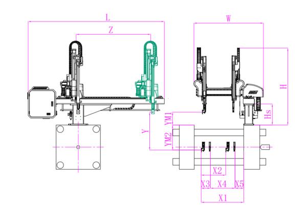
Unit: mm
| X1 | X2 | X3 | X4 | Y | YM1 | YM2 | Z | L | W | H | Payload | 1900 | 734 | 450 | 1150 | 1500 | 450 | 1050 | 2300 | 3120 | 2350 | 2400 | 15kg |
|---|
EOAT Assembly Demonstration -- Two Cavities Parts Picking EOAT with Runner Gripping
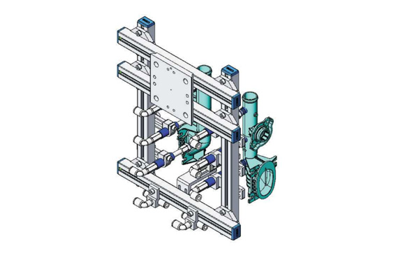
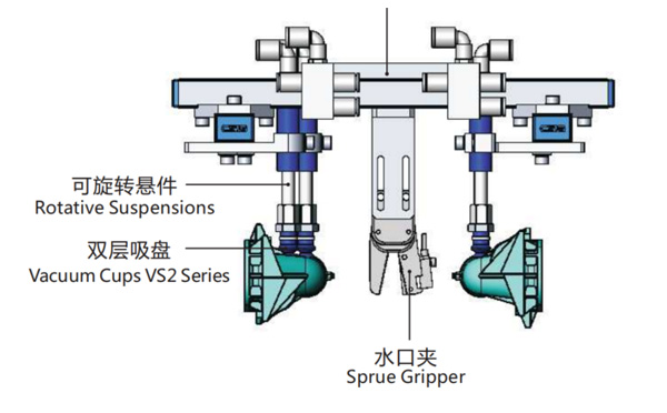
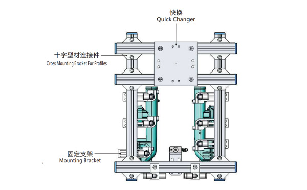
Product Descriptions
Bom List
| Product Name | PN # | Model | Quantity |
|---|---|---|---|
| Quick Changer | 7.Y00175 | QCS-G100 | 1 |
| Sprue Gripper | 8.Y00050 | GR12-12CP | 1 |
| Plugs for Profile | 4.Y00069 | PEP2518 | 10 |
| Cross Mounting Bracket for Profiles | 7.Y00194 | SMBA-2525T | 6 |
| Extruded Profile | 4.Y00455 | PEP2518-1000 | 2 |
| Vacuum Cups VS2 Series | 1.Y03085 | VS2-SA11 | 6 |
| Vacuum Cup Fitting | 7.Y00703 | VM-02-G18 | 6 |
| Rotative Suspensions | 8.Y00061 | VFR1421-G18 | 6 |
| Mounting Bracket | 7.Y00200 | SMBE1-1440T | 6 |
| Connector | 1.Y02510 | APF-M5 | 2 |
| Side Manifold Block | 7.Y00157 | SMB-06M5 | 2 |
| L-Type Threaded HOse Fitting | 1.Y02722 | APL6-01 | 8 |
| Straight Threaded Hose Fitting | 1.Y02725 | APC6-01 | 6 |
For Small and Medium Sized IML Container Producer, Is it Possible to Produce More the One Products with the Same IML Robot?
For manay small and medium sized producer of IML containers it many not be easy to make a decision if to accept the order or not because of the small quantity at the beginning but a huge potential in the future. As the IML robot is a custom made system according to the mold design and the injection molding machine for this mold. But is there any possibility to have one IML robot for a couple of molds? The answer is yes.
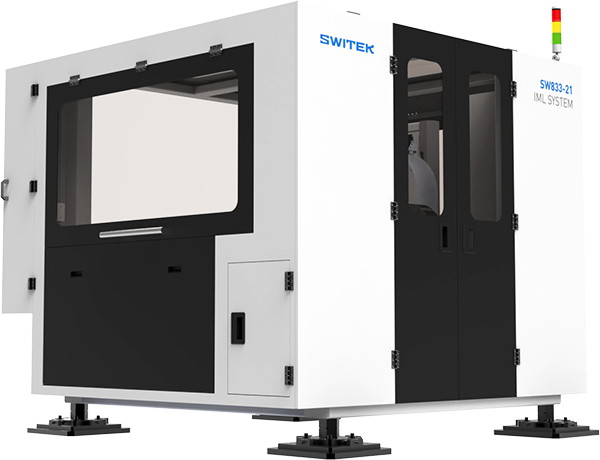
The SW8 series of side entry IML robot is one of which an ideal choice for the small and medium sized producer of IML containers. With exchangeable magazine and stacking unit, the IML robot enable the IML containers producers to produce the small and medium sized IML containers and IML lids by the injection molding machine and the IML robot with simply to have the magazine and EOAT replaced for the new mold. But with this IML robot, how will the IML containers produce to achieve the maximized productivity?
To maximized the productivity of the IML system, the key would be to have the injection molding machines and the IML robots well organized according to the products. To make the change the magazine and EOATs faster, we can have the containers with wraping labeling produced in one IML system and have the 3/5 face labeling containers and the lids produced by another IML system. It's not recommended to have the containers with wraping labeling to be produced by the same IML system with an IML lids, which will need to change both the Magazine and the stacking unit and the time to start the system up would be much longer.
For more advisory of an IML project planning please feel free to contact Adams from SWITEK Automation, your personal consultant of IML system integration.