sales06@switek.biz

+86 186 5927 5869

Shopping

Subscrib to Us
sales06@switek.biz
+86 186 5927 5869
Shopping
Subscrib to Us
Keywords:Panasonic A6 Servo Motor, Panasonic A6 Servo Motor Driver, Panasonic A6 Servo Motor setting instruction
The peripheral equipments will work with the Panasonic A6 series of servo motor and driver in the machineries and automation system, here in this chapter you'll have a list of the applicable peripheral equipments for the Panasonic A6 series of AC motor driver.
List of Peripheral Equipments
| Driver | Voltage *1 | Rated output | Required Power (at the rated load) | Circuit breaker (rated current) | Noise filter (Single phase/3-phase) | Surge absorber (Single phase/3-phase) | Noise filter for signal | Rated operating current of magnetic (Contactor Contact configuration *2) |
|---|---|---|---|---|---|---|---|---|
| MADL☐☐☐☐☐ | Single phase, 100 V | 50 W to 100 W | approx, 0.4 kVA | 10 A | DV0P4170 | DV0P4190 | DV0P1460 | 20 A (3P+1a) |
| Single/3-phase, 200 V | 50 W to 200 W | approx. 0.5 kVA | DV0P4170/DV0PM20042 | DV0P4190/DV0P1450 | ||||
| MBDL☐☐☐☐☐ | Single 100 V | 200 W | approx. 0.5 kVA | DV0P4170 | DV0P4190 | |||
| Single/3-phase, 200 V | 400 W | approx. 0.9 kVA | DV0P4170/DV0PM20042 | DV0P4190/DV0P1450 | ||||
| MCDL☐☐☐☐☐ | Single 100 V | 400 W | approx. 0.9kVA | 15A | DV0PM20042 | DV0P4190 | ||
| Single/3-phase, 200V | 750 W | approx. 1.3kVA | DV0P4190/DV0P1450 | |||||
| MDDL☐☐☐☐☐ | 3-phase, 200V | 1.0 kW | approx. 1.8 kVA | 20 A | DV0P4220 | 30 A (3P+1a) | ||
| 0.9 kW | approx. 1.8 kVA | |||||||
| 1.0 kW | approx. 1.8 kVA | |||||||
| 1.5 kW | approx. 2.3 kVA | |||||||
| MEDL☐☐☐☐☐ | 3-phase, 200V | 2.0 kW | approx. 3.3 kVA | 30 A | DV0PM20043 | DV0P1450 | DV0P1460 RJ8035 (Recommended component *4) | 60 A (3P+1a) |
| 2.5 kW | approx. 3.8 kVA | |||||||
| MFDL☐☐☐☐☐ | 3-phase, 200 V | 2.0 kW | approx. 3.8 kVA | 50 A | DV0P3410 | DV0P1450 | DV0P1460 RJ8035 | 60 A (3P+1a) |
| 3.0 kW | approx. 4.5 kVA | |||||||
| 4.0 kW | approx. 6.0 kVA | 100 A (3P+1a) | ||||||
| 4.5 kW | approx. 6.8 kVA | |||||||
| 5.0 kW | approx. 7.5 kVA |
List of Applicable diameter cables
| Driver | Voltage *1 | Rated output | Required Power (at the rated load) | Diameter and withstand voltage of main circuit cable | Crimp terminal for main circuit terminal block | Diameter and withstand voltage of control power supply cable | Crimp terminal for control power supply terminal block | Diameter and withstand voltage of motor cable *4 | Diameter and withstand voltage of brake cable |
| MADL☐☐☐☐☐ | Single phase, 100 V | 50 W to 100 W | approx. 0.4 kVA | 0.75mm2/AWG18 600 VAC or more | Connection to exclusive connector | 0.75mm2/AWG18 600 VAC or more | Connection to exclusive connector | 0.75mm2/AWG18 600 VAC or more | 0.28mm2/AWG22 to 0.75mm2/AWG18 100 VAC or more |
| Single/3-phase, 200 V | 50 W to 200 W | approx. 0.5 kVA | |||||||
| MBDL☐☐☐☐☐ | Single phase, 100 V | 200 W | approx. 0.5 kVA | ||||||
| Single/3-phase, 200 V | 400 W | approx. 0.9 kVA | |||||||
| MCDL☐☐☐☐☐ | Single phase, 100 V | 400 W | approx.0.9 kVA | ||||||
| Single/3-phase, 200 V | 750 W | approx. 1.8 kWA | |||||||
| MDDL☐☐☐☐☐ | Single/3-phase, 200 V | 0.9 kW | approx. 2.3 kVA | 2.0 mm2/AWG14 600 VAC or more | 2.0 mm2/AWG14 600 VAC or more | 0.75 mm2/AWG18 100 VAC or more | |||
| 1.0 kW | approx. 2.4 kVA | ||||||||
| 1.5 kW | approx. 2.9 kVA |
Note → When use the external regenerative resistor of the option, use the cable with the same diameter as the main circuit cable.
Related page → Noise filter ...P. 7-108 Surge absorber ...P. 7-110 Ferrite coil ...P. 7-111 Motor/brake connector ...P. 2-28
| Driver | Voltage *1 | Rated output | Required Power (at the rated load) | Diameter and withstand voltage of main circuit cable | Crimp terminal for main circuit terminal block | Diameter and withstand voltage of control power supply cable | Crimp terminal for control power supply terminal block | Diameter and withstand voltage of motor cable *4 | Diameter and withstand voltage of brake cable |
|---|---|---|---|---|---|---|---|---|---|
| MEDL☐☐☐☐☐ | 3-phase, 200 V | 2.0 kW | approx. 3.3 kVA | 2.0 mm2/AWG14 600 VAC or more | Connection to exclusive connector | 0.75mm2/AWG18 600 VAC or more | Connection to exclusive connector | 2.0 mm2/AWG14 600 VAC or more | 0.75mm 2/AWG18 100 VAC or more |
| 2.4 kW | approx. 4.5 kVA | ||||||||
| MFDL☐☐☐☐☐ | 3-phase, 200 V | 3.0 kW | approx. 4.5 kVA | 3.5 mm2/AWG 12 600 VAC or more | 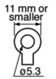 Terminal block M5 | Terminal block M5 | 3.5mm 2/AWG12 600 VAC or more |
*1 Select peripheral equipments for single/3phase common specification according to the power source.
*2 For the external dynamic brake resistor, use the magnetic contactor with the same rating as that for the main circuit.
*3 When use the external regenerative resistor of the option (DV0PM20058, DV0PM20059), use the cable with the same diameter as the main circuit cable.
*4 Use these products to suit a standard.
 marked).
| Driver | Terminal block screw | Terminal cover fastening screw | |||
|---|---|---|---|---|---|
| Frame | Terminal name | Norminal size | Fastening torque (N•m)Note 1 | Nominal size | Fastening torque (N•m)Note 1 |
| F | L1, L2, L3, L1C, L2C, P, RB, B, N, U, V, W | M5 | 1.0 to 1.7 | M3 | 0.19 to 0.21 |
| Driver frame | Terminal block screw | Connector to host controller (X4) | ||
|---|---|---|---|---|
| Nominal size | Fastening torque (N•m)Note 1 | Nominal size | Fastening torque (N•m)Note 1 | |
| A to E | M4 | 0.7 to 0.8 | M2.6 | 0.3 to 0.35 |
| F | M5 | 1.4 to 1.6 | ||
Caution → Note:1

SW6310S-20
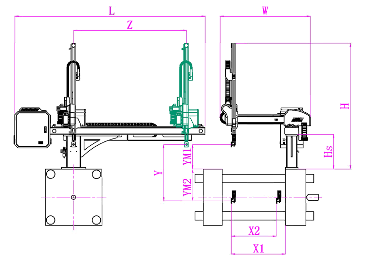
Unit: mm
| X1 | X2 | X3 | X4 | Y | YM1 | YM2 | Z | L | W | H | Payload | 980 | 820 | 0 | 0 | 1000 | 235 | 765 | 1580 | 2640 | 1500 | 1930 | 3kg |
|---|
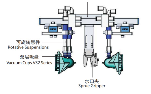
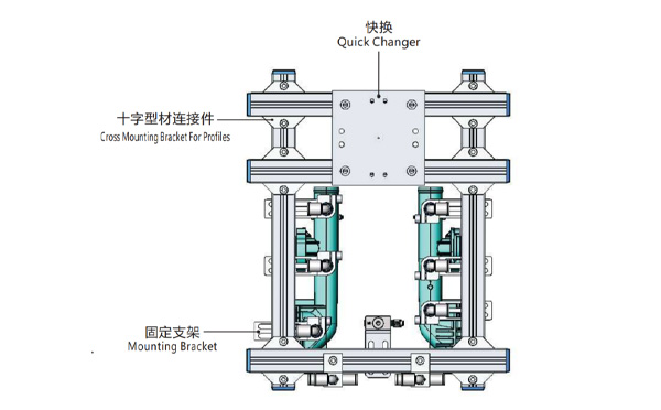
EOAT Assembly Demonstration -- Two Cavities Parts Picking EOAT with Runner Gripping
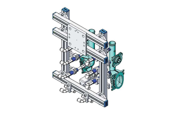
Product Descriptions
Bom List
| Product Name | PN # | Model | Quantity |
|---|---|---|---|
| Quick Changer | 7.Y00175 | QCS-G100 | 1 |
| Sprue Gripper | 8.Y00050 | GR12-12CP | 1 |
| Plugs for Profile | 4.Y00069 | PEP2518 | 10 |
| Cross Mounting Bracket for Profiles | 7.Y00194 | SMBA-2525T | 6 |
| Extruded Profile | 4.Y00455 | PEP2518-1000 | 2 |
| Vacuum Cups VS2 Series | 1.Y03085 | VS2-SA11 | 6 |
| Vacuum Cup Fitting | 7.Y00703 | VM-02-G18 | 6 |
| Rotative Suspensions | 8.Y00061 | VFR1421-G18 | 6 |
| Mounting Bracket | 7.Y00200 | SMBE1-1440T | 6 |
| Connector | 1.Y02510 | APF-M5 | 2 |
| Side Manifold Block | 7.Y00157 | SMB-06M5 | 2 |
| L-Type Threaded HOse Fitting | 1.Y02722 | APL6-01 | 8 |
| Straight Threaded Hose Fitting | 1.Y02725 | APC6-01 | 6 |
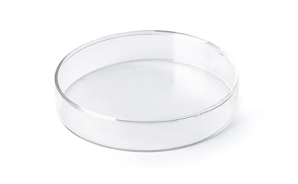
What Would be a Preferable Mould Layout Design for a Petri Dish Packing System?
SWITEK is now providing two kinds of solutions for Petri dish packing, one is a packing system with top entry picking robot and the other is a system with a side entry picking robot. The petri dish producer can decide which solutions is better according to the layout design of the workshop.
Traditionally the mould layout design for the Petri dish production will have the top and base integrated into the same mould which could be 2 + 2, 4 + 4 or 8 + 8 with the cover to the top of the mould. The cover on top design is preferable to an automation system of Petri dish packing.
For an automation system of Petri dish packing, the best is to have a turn-key solutions of Petri dish packing of which SWITEK will have the whole system well tested before delivery to ensure that the automation system which you received is a ready to work one to reduce the cost of sytem start up.